background image

Introduction  


03/2008 

0351709

  -  PEM-T3


3


Table of contents 

Page 

1.


Safety regulations ....................................................................................................... 5


1.1


Safety hints.................................................................................................................... 5


1.2


EC Declaration of conformity......................................................................................... 6


2.


Preparing the spray gun ............................................................................................. 7


2.1


Select the suitable nozzle system ................................................................................. 7


2.2


Connecting the spray gun ............................................................................................. 7


2.3


Grounding......................................................................................................................8


3.


Working with the spray guns ..................................................................................... 9


3.1


Start up the spray gun ................................................................................................... 9


3.2


Switching off the spray gun ........................................................................................... 9


3.3


Carrying out a change of color .................................................................................... 10


4.


Maintenance and cleaning........................................................................................ 11


4.1


Replacing the spray gun.............................................................................................. 11


4.2


Cleaning the spray gun and replace the wear parts.................................................... 12


4.3


Mounting the gun extension ........................................................................................ 13


4.4


Disposal.......................................................................................................................15


5.


Rectification of malfunctions ................................................................................... 16


6.


Technical data ........................................................................................................... 17


7.


Warranty..................................................................................................................... 18


8.


Scope of delivery and spare parts lists................................................................... 19


8.1


How to order................................................................................................................ 19


8.2


Scope of delivery and spare parts list of PEM-T3 ....................................................... 19


8.3


Charging body (complete) ........................................................................................... 20


8.4


Wide fan spray nozzle ................................................................................................. 20


8.5


Gun extension ............................................................................................................. 21


8.6


Charging body of PEM-T3 300.................................................................................... 22


8.7


Outer tube ................................................................................................................... 23


Summary of Contents for PEM-T3

Page 1: ...ner group com Operating Manual Tribo Manual Spray Gun DANGER High Voltage Turn power off before servicing CAUTION Read rules for safe operation and instructions carefully pemt3_0000 0351967 PEM T3 C E...

Page 2: ...ating This spray gun can be operated with the following control units EPG 2008 with powder injector PI P1 EPG D1 with powder injector PI F1 Control unit Bravo with powder injector PI FM1 The powder fe...

Page 3: ...ray gun 9 3 3 Carrying out a change of color 10 4 Maintenance and cleaning 11 4 1 Replacing the spray gun 11 4 2 Cleaning the spray gun and replace the wear parts 12 4 3 Mounting the gun extension 13...

Page 4: ...ention to the parts marked by the following symbols Follow the instructions exactly in the interests of both your own safety and the correct functioning of the unit Warning This symbol draws attention...

Page 5: ...average powder air concentration may not exceed 10 g m Over sprayed powder must be reliably collected Adhere to the instructions given by the manufac turers and to the prevalent local laws on the envi...

Page 6: ...commended in the operating manual may create a hazard to personal safety Use only original Wagner replacement parts Alteration or repair of Wagner original spare parts may cause fatal accidents or exp...

Page 7: ...dely spread flat powder cloud For powder quantities from 50 150 g min Wide fan spray nozzle Difficult workpieces Undercuts Profiles Widely spread flat powder cloud For powder quantities from 100 250 g...

Page 8: ...easons the spray gun must be properly grounded This occurs through the electrical cable 0203_ doc Good grounding of the workpiece is also necessary for optimum powder coating A poorly grounded workpie...

Page 9: ...A 3 2 Switching off the spray gun The spray gun is switched off in different ways depending on the type of powder injector Hint The spray gun should be blown through flushed and cleaned from powder d...

Page 10: ...er s injector connection so that no powder can be delivered during flushing Press the trigger on the spray gun so that the spray gun is blown free of powder Switch the control unit off and secure it a...

Page 11: ...performed outside the hazard area and in a suitable place by specialist personnel The wearing parts in the spray gun marked in the spare parts list with must be regularly checked and if necessary repl...

Page 12: ...e nozzle body 4 from the gun housing 3 Carefully pull out the charging body 5 Check the removed parts for wear The entire charging body can be replaced with a new one during this procedure It is also...

Page 13: ...sion the spray gun must always be thoroughly clean It is even better to use a new spray gun 1 2 3 P_00715 Pull the deflector cone fan spray nozzle 1 from the nozzle body 3 Unscrew the outer nut 2 from...

Page 14: ...t outer tube 5 into the gun housing and secure it with outer nut 2 6 7 1 P_00718 Insert charging body 6 into the outer tube 5 and push it in as far as it will go Push adapter 7 onto outer tube 5 as fa...

Page 15: ...tronic equipment and implementation in accordance with national law this product is not to be disposed of together with household waste material but must be recycled in an environmentally friendly way...

Page 16: ...ate or no ground See chapter Grounding Powder outlet uneven or inadequate Soiling Powder sintering or powder conveying parts in spray gun worn Blow through parts carrying powder Feed air dosage air ra...

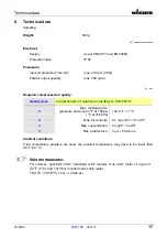
Page 17: ...ssed air quality according to ISO 8573 1 5 Max residual water pressure dew point in F at 100 psi C at 700 kPa 44 6 F 7 C 2 Max oil contents 0 1 mg oil m3 0 1 oz ft3 3 Max concentration 5 mg m3 5 oz ft...

Page 18: ...performed by anyone other than a Wagner authorized service center or 3 Damages or defects caused by or related to abrasion corrosion abuse misuse negligence accident normal wear faulty installation o...

Page 19: ...owing informa tion is necessary Invoicing address Delivery address Name of contact persons for check back Type of delivery Quantity ordered article number and designation 8 2 Scope of delivery and spa...

Page 20: ...ing tube 10 0260476 Support ring 11 0260470 Rod 12 0260463 Central air supply 13 0260469 Deflector cone rod 14 0260632 Air nozzle complete 0260629 14 13 12 11 8 7 9 10 6 0260629_et Wearing part 8 4 Wi...

Page 21: ...s lists 03 2008 0351709 PEM T3 21 8 5 Gun extension 2 1 P_00719 4 3 Item Art No Designation 0260934 Gun extension 300 mm 1 0260935 Charging body PEM T3 ET 2 0260936 Outer tube PEM T3 ET 3 0259474 Defl...

Page 22: ...5 5 10 6 7 P_00720 Item Art No Designation 0260935 Charging body PEM T3 300 1 0260632 Air nozzle complete 2 0260463 Central air supply 3 0260469 Deflector cone rod 4 0260470 Rod 5 0260471 Charging tu...

Page 23: ...Scope of delivery and spare parts lists 03 2008 0351709 PEM T3 23 8 7 Outer tube 1 2 P_00721 Item Art No Designation 0260936 Outer tube T3 300 ET 1 0260655 Outer tube T300 2 0260656 Powder tube...

Page 24: ...Notes 24 0351709 PEM T3 03 2008...

Page 25: ...Notes 03 2008 0351709 PEM T3 25...

Page 26: ...Notes 26 0351709 PEM T3 03 2008...

Page 27: ...x 49 0 7544 505200 Fax 31 0 30 2410765 Belgium Denmark Estee Industries WAGNER Powder Systems Scvandinavia Leenbeekstraat 9 Juupajokivej 8 B 9770 Kruishoutem DK 8850 Bjerringbro Phone 32 0 9 3885410 P...

Page 28: ...ne Shanghai 200436 Phone 86 0 2166521858 Fax 86 0 2166529819 France J Wagner France SARL B P 75 5 Avenue du 1er Mai F 91122 Palaiseau C dex Phone 33 0 825 011111 Fax 33 0 1 69817257 Italy Spain WAGNER...

Reviews: