background image

13

PEA-C4XL-S

OPERATING MANUAL

VERSION 03/2014

ORDER NUMBER DOC2345334

4.2.1 

SAFE HANDLING OF WAGNER POWDER SPRAY DEVICES

4.2.2 

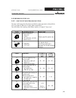
GROUNDING THE DEVICE

4.2.3 

ACCESSORIES AND SPARE PARTS

4.2 

SAFETY INSTRUCTIONS FOR STAFF

  Always follow the information in this manual, particularly the general safety instructions 

and the warning instructions.

 Always follow local regulations concerning occupational safety and accident 

prevention.

  Under no circumstances may people with pacemakers enter the area where the high-

voltage fi eld between the spray gun and the work piece to be coated builds up!

  Do not point spray guns at people.
  Before all work on the device, in the event of work interruptions and functional faults:

- Switch off  the energy/compressed air supply.
- Secure the spray gun against actuation.
- Relieve pressure on spray guns and device.
- In case of functional faults: Identify and correct the problem, proceed as described 

in the "Fault Rectifi cation" chapter.

The electrostatic charge may, in certain cases, give rise to electrostatic charges on the 
device. This may result in the formation of sparks or fl ames when discharging.

  Ensure that the device is grounded before each coating process.
  Ground the work pieces to be coated.
 Ensure that all persons inside the working area are grounded, e.g. by wearing 

electrostatically conductive shoes.

  The functionality of grounding cables must be checked regularly (see EN 60204).

  Only use an original Wagner powder hose.

Summary of Contents for PEA-C4XL-S

Page 1: ...0102 II 2 D EEx 2mJ 85 C P_02330 Automatic Powder Spray Gun PEA C4XL S Version 03 2014 Translation of the Original Operating Manual ...

Page 2: ......

Page 3: ...quipment 12 4 1 2 Staff Qualifications 12 4 1 3 Safe Work Environment 12 4 2 Safety Instructions for Staff 13 4 2 1 Safe Handling of WAGNER Powder Spray Devices 13 4 2 2 Grounding the Device 13 4 2 3 Accessories and Spare Parts 13 4 2 4 Cleaning and Maintenance 14 4 2 5 Handling Powder Lacquers 14 4 3 Note on Safe Discharges 15 4 4 Protective and Monitoring Equipment 16 4 4 1 Release Guns High vol...

Page 4: ...tenance Procedures 39 8 2 4 Replacing the Spray Gun 40 8 3 Cleaning the Gun and Dismantling the Flat Spray Nozzle 42 8 4 Replacing the Protective Wedge 43 8 5 Fitting the Round Spray Nozzle 45 8 6 Assembling the Angle Adapter 47 8 6 1 Removing the Nozzle and Electrode Holder 47 8 6 2 Fitting the Angle Adapter 48 8 6 3 Replacement of the Wearing Parts 48 8 7 Assembling the Corona Star 50 8 8 Corona...

Page 5: ... C4XL S Corona Automatic Gun 66 13 3 C4 R Electrode Holder with Nozzles 67 13 4 WA90 C4 Angle Adapter 68 13 5 WA60 C4 Angle Adapter 69 13 6 WA30 C4 Angle Adapter 70 14 DECLARATION OF WARRANTY AND CONFORMITY 71 14 1 Important Notes Regarding Product Liability 71 14 2 Warranty Claim 71 14 3 Declaration of Conformity 72 Table of Contents ...

Page 6: ...e imminent danger Non observance may result in death or serious injury Caution a possibly hazardous situation Non observance may result in minor injury Note provides information about particular characteristics and how to proceed Notice a possibly hazardous situation Non observance may result in material damage This notice warns you of a hazard Possible consequences of not observing the warning in...

Page 7: ...4 1 3 LANGUAGES The operating manual is available in the following languages Language Order No Language Order No German 2345333 English 2345334 Italian 2345335 1 4 ABBREVIATIONS Number of pieces Position Marking in the spare parts lists Order No Order number Spare part ...

Page 8: ...ed in potentially explosive areas zone 22 See Chapter 3 1 Explosion Protection Identification 2 4 SAFETY PARAMETERS The powder spray gun is only suited to the application of powder paint J Wagner AG forbids any other use The powder spray gun may only be operated under the following conditions if the operating staff have previously been trained on the basis of this operating manual the safety regul...

Page 9: ...SKS Residual risks are risks which cannot be excluded even in the event of correct use If necessary warning and prohibition signs at the relevant points of risk indicate residual risks Residual risk Source Consequences Specific measures Lifecycle phase Skin contact with powder lacquers and cleaning agents Handling powder lacquers and cleaning agents Skin irritations Wear protective clothing Operat...

Page 10: ...ufacturer J Wagner AG CH 9450 Altstätten II 2 D EEx 2mJ 85 C CE European Communities 0102 Number of notified body which is involved in the production monitoring phase E according to European standard Ex Symbol for explosion protection II Device class II 2 Category 2 D Ex atmosphere dust 2mJ Maximum ignition energy 2 mJ 85 C Maximum surface temperature Incorrect use of the spray gun Risk of injury ...

Page 11: ...h the following indications The equipment may only be operated by trained staff Before starting cleaning the spray gun or carrying out any other work in the spray area the high voltage must be shut down in such a way that it cannot be activated again by actuating the trigger of the spray gun Use only metallic tanks for cleaning fluids Preferably use solvents with the highest possible flash point h...

Page 12: ...t the device is operated maintained and repaired only by trained persons The floor in the working area must be electrostatically conductive measurements according to EN 1081 and EN 61340 4 1 The footwear worn by the operators must comply with the requirements of EN ISO 20344 The measured insulation resistance must not exceed 100 megohms The protective clothing including gloves must comply with the...

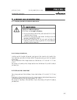
Page 13: ...all work on the device in the event of work interruptions and functional faults Switch off the energy compressed air supply Secure the spray gun against actuation Relieve pressure on spray guns and device In case of functional faults Identify and correct the problem proceed as described in the Fault Rectification chapter The electrostatic charge may in certain cases give rise to electrostatic char...

Page 14: ...hey can be accessed Most flammable solvents have an ignition energy of around 0 24 mJ or 60 nC The cleaning agent s flash point must be at least 15 K above the ambient temperature Only mobile industrial vacuum cleaners of design 1 see EN 60335 2 may be used to remove dust deposits When preparing or processing the powder and cleaning the device take note of the processing regulations laid down by t...

Page 15: ...the grounded work piece This luminous discharge does not involve any ignition energy and has no effect on system handling When the electrode approaches the work piece the control unit automatically reduces the high voltage to a safe value If you touch plastic parts of the spray gun with your finger harmless discharges may occur due to the high voltage field around the spray gun so called brush dis...

Page 16: ...se conditions is not fulfilled the high voltage is switched off immediately After the fault has been eliminated and acknowledged the enabling mechanism can be selected again An automatic switch on is prevented by the hardware locking Incorrect use Risk of injury and damage to the device Protective and monitoring equipment must not be removed modified or rendered unusable Regularly check for perfec...

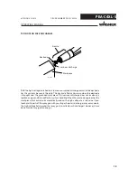
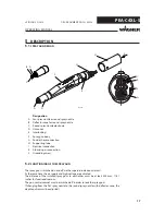
Page 17: ...ube I Electrical connection K Atomizing air connection L Grounding screw 5 2 FUNCTIONING OF THE SPRAY GUN The spray gun is switched on and off via the superordinated control unit At the same time the air supply and high voltage are activated The distance of the installed spray guns to each other must be at least 300 mm 11 81 inches for functional reasons The gun control cabinet must be switched of...

Page 18: ...MPa 43 51 psi Powder output quantity maximum 450 g min maximum 0 99 lbs min Ambient conditions Operating temperature range 5 45 C 41 113 F Relative humidity 75 5 3 TECHNICAL DATA Outgoing air containing oil Risk of poisoning if inhaled Provide compressed air free from oil and water Quality Standard 3 5 2 according to ISO 8573 1 3 5 2 5 μm 7 C 44 6 F 0 1 mg m WARNING Ambient conditions If low melti...

Page 19: ...MANUAL VERSION 03 2014 ORDER NUMBER DOC2345334 5 3 1 DIMENSIONS Measurement mm inch A 30 1 18 B 400 15 75 C 1 100 43 31 D 60 2 36 E 72 2 83 Measurement for installation dimension C calculation when utilizing a round spray nozzle with deflector cone ...

Page 20: ...347535 Conformity certificate 1 2345333 Operating manual German 1 see Chapter 1 3 Operating manual in local language 5 5 SCOPE OF DELIVERY 5 4 PERMITTED ACCESSORIES Only the accessories listed in this operating manual may be connected to the PEA C4XL S powder spray gun The accessories listed in Chapter 12 were included in the EC type examination and are approved for use with the gun ...

Page 21: ...N CONDITIONS The air temperature at the installation site must be between 0 C and 35 C 32 F and 95 F Depending on the powder lacquer used the maximum permissible ambient temperature for reliable operation can be significantly below 40 C 104 F The relative air humidity at the installation site must be between 10 and 95 without condensation Incorrect installation operation Risk of injury and damage ...

Page 22: ... high penetration capability for profile parts high stability F4 Wide flat spray nozzle for high powder application slow powder cloud 200 Total air 4 5 Nm h 150 400 good atomization specially for extensive work pieces The process of changing from the fan spray nozzle to a round spray nozzle with a deflector cone is described in Chapter 8 5 Fitting a Round Spray Nozzle You will find the article num...

Page 23: ...e flat spray nozzle for high powder application slow powder cloud 200 Total air 4 5 Nm h 150 400 good atomization specially for extensive work pieces 1 Nozzles are labeled on the back Deflector cone Application Distance to work piece Powder discharge mm g min R20 100 300 30 250 20 mm Smaller flat parts R28 100 300 50 250 28 mm Medium sized flat parts Lateral application with Z axis ...

Page 24: ...24 PEA C4XL S OPERATING MANUAL VERSION 03 2014 ORDER NUMBER DOC2345334 ...

Page 25: ...n 2 Turning the locking nut 2 in a clockwise direction up to the stop and pull the hose coupling 3 out of the coupling piece 4 Connecting the hose coupling 3 Insert the hose coupling 3 into the coupling piece 4 and turning the locking nut 2 counterclockwise up to the stop 4 Press the O ring 1 into the groove again securing function Note Slide the powder hose as much as possible up to the stop onto...

Page 26: ...onal putting into operation Risk of injury Before any work on the device in the event of work interruptions and malfunctions Switch off the energy compressed air supply Relieve spray gun and device pressure Secure the spray gun against actuation In the event of malfunctions remedy the fault as described in the Troubleshooting chapter WARNING ...

Page 27: ...Chapter 6 5 5 Connect the atomizing air hose 5 to connection K on the spray gun and to the control unit 6 Connect the grounding cable 6 to grounding screw L on the spray gun and to the signal ground 7 Press locking button 1 and supporting tube 2 forwards on the spray gun housing up to stop The locking button 1 must snap into place in the drilled hole in supporting tube 2 8 Fasten gun on the gun ca...

Page 28: ...booth conveyor system and suspension on the part of the building site in accordance with the operating manual or the manufacturer s information and grounding of all conductive parts of the system The resistance to ground of every work piece s locating point must not exceed 1 MΩ megohm measurement voltage must be 500 or 1000 V Sparks between conveyor conveyor hooks hangers and work piece can occur ...

Page 29: ...NDING THE POWDER COATING SYSTEM 1 Only use mains cables with grounding strand 2 Connect grounding cable with signal ground 3 Remove all paint from hooks and other hanger parts 4 Do not wear non conducting gloves 5 Wear electrostatically conductive shoes 6 The floor must be electrostatically conductive ...

Page 30: ...ff must be familiar with the provisions of European standard DIN EN 50177 WARNING Incorrect operation Risk of injury and damage to the device If contact with powder products or cleaning agents causes skin irritation appropriate precautionary measures must be taken e g wearing protective clothing The footwear worn by operating staff must comply with EN ISO 20344 The measured insulation resistance m...

Page 31: ... the automatic flushing mode please proceed as follows Procedure 1 The atomizing air has to remain open to prevent powder from penetrating into the atomizing air channel and the cascade compartment during the flushing process Switch off the powder feed and the high voltage generation 2 If you do not want to modify the settings of the feed and dosage air to continue coating with the same powder clo...

Page 32: ...Note To minimize the wear on the wearing parts the total feed air and dosing air should be under 5 Nm h The atomizing air should be adjusted for the fan spray nozzle to 0 1 Nm h round spray nozzle with deflector cone to 0 2 Nm h 2 Adjust the powder quantity and the powder speed on a test piece 7 6 OPTIMIZING THE POWDER CLOUD FOR YOUR COATING ...

Page 33: ...off the system Disconnect the powder hose from the spray gun Blow through the spray gun using the air gun and thus remove any powder residues Switch off the system and secure against unauthorized reactivation 3 Before starting to connect the powder hose again all parts carrying powder must be thoroughly cleaned 4 The spray gun is ready for use again Dust formation Danger of poisoning Danger due to...

Page 34: ...g from there Further details are contained in the powder center s operating manual Note During a paint change the nozzle system does not necessarily have to disassembled Powder supply hose coupling may be hurled around Risk of injury and damage to the device Check whether the hose is correctly attached to the hose coupling Completely lock the hose coupling and secure it with an O ring WARNING ...

Page 35: ...to achieve smoother coating the protective wedge is now in the vertical position It is possible to change this position as needed for special applications On the nozzle body and electrode holders there are X markings The position can be changed as required in 15 increments and later reproduced The union nut has to be removed for exact positioning An adjustment tool is provided for the flat spray n...

Page 36: ...s Danger to life and damage to the device Before starting cleaning or other manual work the high voltage mustbeshutdownandlockedtopreventitfrombeingswitched back on Use only electrically conductive tanks for cleaning liquids Ground the tank Preference should be given to non flammable cleaning fluids Flammable cleaning liquids may only be used if after switching off the high voltage all high voltag...

Page 37: ... 4 must be adhered to for all cleaning work 8 1 3 CLEANING PROCEDURES Incorrect maintenance Risk of injury and damage to the device If contact with powder products or cleaning agents causes skin irritation appropriate precautionary measures must be taken e g wearing protective clothing The footwear worn by operating staff must comply with EN ISO 20344 The measured insulation resistance must not ex...

Page 38: ... MAINTENANCE STAFF 8 2 2 SAFETY INSTRUCTIONS Incorrect maintenance repair Risk of injury and damage to the device Have repairs and part replacements carried out only by specially trained staff or a WAGNER service center Before all work on the device and in the event of work interruptions Switch off the energy compressed air supply Relieve spray gun and device pressure Secure the spray gun against ...

Page 39: ...r 4 must be adhered to for all maintenance work 8 2 3 MAINTENANCE PROCEDURES Incorrect maintenance Risk of injury and damage to the device If contact with powder products or cleaning agents causes skin irritation appropriate precautionary measures must be taken e g wearing protective clothing The footwear worn by operating staff must comply with EN ISO 20344 The measured insulation resistance must...

Page 40: ...onal putting into operation Risk of injury Before any work on the device in the event of work interruptions and malfunctions Switch off the energy compressed air supply Relieve spray gun and device pressure Secure the spray gun against actuation In the event of malfunctions remedy the fault as described in the Troubleshooting chapter WARNING ...

Page 41: ...er feed hose 4 from connection G on the spray gun The handling of the hose coupling is described in Chapter 6 5 5 Disconnect the atomizing air hose 5 from connection K on the spray gun 6 Detach the grounding cable 6 from grounding screw L on the spray gun 7 Connect electrical cable 3 to connection I on the new spray gun 8 Connect the powder feed hose 4 to connection G on the spray gun 9 Connect th...

Page 42: ...un housing 5 Note Do not damage the electrode holder when pulling it out and inserting it 4 Remove powder residues from the parts removed and from the spray gun Note Never place the spray gun or parts of the spray gun in cleaning agent As a rule the protective wedge needs to be checked for wear and replaced if necessary New protective wedge Worn protective wedge It is recommended to replace the pr...

Page 43: ...hension Procedure 1 Guide wedge tool 1 into electrode holder 3 up to stop 2 Pull the protective wedge 2 out of the electrode holder 3 using the wedge tool 1 3 Press the protective wedge 2 sideways out of wedge tool 1 manually without tool Note A wedge tool is available to prevent the protective wedge from being damaged when dismantling and inserting You will find the necessary wearing parts and sp...

Page 44: ...e X mark rotate the wedge tool a little until it can be pushed up to the mark The mark X must be flush with the Y end of the electrode holder 4 The protective wedge is now correctly assembled and the wedge tool can be pulled out of the electrode holder The protective wedge remains inserted in the electrode holder Note The same wedge tool is used to insert the protective wedge 1 Wedge tool 2 Protec...

Page 45: ...using 5 Note Do not damage the electrode holder when pulling it out and inserting it 4 Remove powder residues from the parts removed and from the spray gun 5 After long periods of operation or having replaced the protective wedge repeatedly it is also recommended to check the powder tube for wear and replace if necessary You will find the necessary wearing parts and spare parts in Chapter 13 Spare...

Page 46: ...electrode holder 6 into spray gun housing 5 6 Slide deflector cone sleeve 7 onto electrode holder 6 7 Align the X and Y marks 8 Fasten union nut 1 9 Slide deflector cone 8 over deflector cone sleeve 7 10 The spray gun is ready for use again Electrode tip Risk of injury Take care when fitting the C4 R electrode holder CAUTION ...

Page 47: ...ted A WA90 C4 WA 60 C4 or WA30 C4 angle adapter is necessary to perform the change as listed in Chapter 12 Accessories Note A flat spray nozzle as well as a round spray nozzle can be fitted to the angle adapter 8 6 1 REMOVING THE NOZZLE AND ELECTRODE HOLDER Procedure 1 Unscrew union nut 1 from gun housing 5 2 Pull flat spray nozzle 2 off electrode holder 3 3 Carefully remove electrode holder 3 fro...

Page 48: ...Push angle adapter 5 onto the gun body and gently screw threaded sleeve 6 3 Swivel angle adapter 5 into the desired position and then tighten threaded sleeve 6 well 8 6 3 REPLACEMENT OF THE WEARING PARTS Procedure 1 Loosen threaded sleeve 1 and separate angle adapter 2 from gun body 3 2 Loosen union nut 4 3 Pull out electrode holder 5 together with nozzle 6 from nozzle insert 7 Note Do not damage ...

Page 49: ...ly and remove any powder residues 10 Install nozzle insert 7 as shown in magnified figures Y1 and Y2 in such a way that the pin B1 is guided into the hole A1 11 Install connecting element 11 within the angle piece 12 as shown in the magnified figure Z in such a way that the pin B2 is guided into the hole A2 12 Screw threaded sleeve 8 and locking sleeve 9 with mounting tool 10 and tighten them well...

Page 50: ...ousing B 3 Screw the new nut C for the Corona Star D onto the spray gun housing and tighten well 4 Dismount the Corona Star H from spray gun housing B 5 Fasten the cable guide onto the cover plate F using screw E 6 Slide the Corona Star G onto the spray gun housing B Note Check whether the grounding is assured 7 The spray gun is ready for use again Danger from electric current Risk of injury and d...

Page 51: ...apter direction of fitting shown is only an example 4 Fasten the connection cable 3 on the spray gun housing Note Check whether the grounding is assured 5 The spray gun is ready for use again Note When converting the gun in the normal version fit again without a Mini Corona Star 1 angle adapter Danger from electric current Risk of injury and damage to the device Only trained personnel may modify t...

Page 52: ...N ACCORDANCEWITH DIN EN 50177 2010 04 If the system is used for electrostatic coating with flammable coating powders testing should be undertaken in accordance with DIN EN 50177 2010 04 as per Table 3 and Table 4 The inspection types and intervals are described in the following chapters ...

Page 53: ...ical ventilation is not working eff ectively SP FI Test whether the system is safely stopped and the product supply supply air and high voltage are switched off when the ventilation is shut down annually 3 Protection against ignition of fl ammable cleaning agents If fl ammable cleaning fl uids are used all parts carrying high voltage must be discharged to a discharge energy of less than 0 24 mJ on...

Page 54: ...ance to ground of work piece s locating point The resistance to ground of every work piece s locating point must not exceed 1 megohm measurement voltage must be 500 or 1000 V The design of the work piece receiver must ensure that the adapters remain grounded during coating SP ME CI Measure resistance to ground work piece receiver ground potential max 1 MOhm 1000 V weekly 6 Further inspections Depe...

Page 55: ...55 PEA C4XL S OPERATING MANUAL VERSION 03 2014 ORDER NUMBER DOC2345334 ...

Page 56: ...ISPOSAL 10 1 DISASSEMBLY WARNING Incorrect disassembly Risk of injury and damage to the device Before starting disassembly Switch off the energy compressed air supply Ensure that all system components are grounded Secure system against being switched back on without authorization Observe the operating manuals for any work ...

Page 57: ...in an environmentally friendly way Please contact one of our service points one of our representatives or us directly to arrange this NOTICE Procedure 1 Switch off the high voltage generation on the control unit close the compressed air supply and relieve the system of pressure 2 Press locking button 1 and carefully remove the gun from supporting tube 2 3 Disconnect electrical cable 3 from connect...

Page 58: ...stem components are grounded Secure the device against being switched back on without authorization Observe the operating and service manuals at all times when carrying out work DANGER Incorrect maintenance repair Danger to life and damage to the device Wagner devices protective systems and safety monitoring and control equipment may only be maintained repaired as defined in Directive 94 9 EC ATEX...

Page 59: ...ck spray Insufficient or no grounding See Chapter 6 7 Grounding Powder outlet uneven or inadequate Contamination Blow through parts carrying powder Powder sintering Clean parts carrying powder Feed device contaminated See operating manuals for the related devices connected Feed air dosing air ratio incorrect Adjust at control module resp control unit Wear on powder injector nozzle Replace worn par...

Page 60: ... 12ACCESSORIES 12 1 FLAT SPRAY NOZZLES Order No Designation 390324 Flat spray nozzle F1 390325 Flat spray nozzle F2 390326 Fan spray nozzle F3 2311889 Flat spray nozzle F4 390331 Wide flat spray nozzle HPO 1 12 2 DEFLECTOR CONE FOR ROUND SPRAY NOZZLE Order No Designation 390207 Deflector cone 20 mm 390208 Deflector cone 28 mm ...

Page 61: ...03 2014 ORDER NUMBER DOC2345334 Order No Designation 1 1 390918 Corona Star complete 2 1 260296 Corona Star electrode 3 1 390319 Union nut Wearing parts 12 3 CORONA STAR RETROFIT SET 12 4 CORONA STAR WA C4 Pos K Order No Designation 1 1 2306335 Corona Star WA C4 ...

Page 62: ...ctive wedges Only available as a set 12 6 ELECTRIC CABLES AND HOSES Order No Designation Application 351216 Electrical cable 5 m for connecting the spray gun to the high voltage generator 351217 Electrical cable 10 m 351215 Electrical cable 20 m 2307502 Powder hose 11 mm for powder feed 2310700 Powder hose 12 mm 9982079 Hose 6x1 Atomizing air connection ...

Page 63: ...OPERATING MANUAL VERSION 03 2014 ORDER NUMBER DOC2345334 12 7 ANGLE ADAPTER Order No Designation 390927 Angle adapter WA30 C4 390930 Angle adapter WA60 C4 390931 Angle adapter WA 90 C4 Order No Designation 390939 Mounting tool WA C4 ...

Page 64: ...r No Designation 390940 Powder measuring bag complete For measuring powder quantities for the C4 gun generation The powder measuring bag is slid onto the nozzle Risk of explosion due to electrostatic charging Danger to life and damage to the device Only use powder measuring bag when high voltage is switched off DANGER ...

Page 65: ... Billing address Delivery address Name of the person to be contacted in the event of any queries Type of delivery normal mail express delivery air freight courier etc Wearing parts Note These parts are not covered by warranty terms Not part of the standard equipment but available as a special accessory Incorrect maintenance repair Risk of injury and damage to the device Have repairs and part repla...

Page 66: ...on nut 3 1 390324 Flat spray nozzle F1 4 1 390915 Electrode holder 5 1 390310 Wedge 6 1 390911 Powder tube C4 ET 7 1 390957 Mini Corona Star 8 1 2345327 XL S ET supporting tube 9 1 2344114 Rear powder tube 10 1 9971131 O ring 22x3 11 1 390954 Coupling piece 12 1 390955 Hose take up D10 D12 13 1 390342 Adjustment tool for flat spray nozzles Wearing parts Not part of the standard equipment but avail...

Page 67: ... C4 R electrode holder complete 2 1 390916 C4 R electrode holder 3 1 390310 Wedge 4 1 390313 Deflector cone sleeve 5 1 390207 R20 deflector cone 20 mm 0 79 inch 6 1 390208 R28 deflector cone 28 mm 1 10 inches Wearing parts Not part of the standard equipment but available as a special accessory Only available as a set 13 3 C4 R ELECTRODE HOLDER WITH NOZZLES ...

Page 68: ...le adapter 2 1 390947 WA C4 ET union nut 3 1 390933 WA90 C4 ET nozzle insert 4 1 390942 WA90 C4 ET elbow fitting 5 1 390932 WA C4 ET connecting element 6 1 390946 WA C4 ET locking sleeve 7 1 390945 WA C4 ET threaded sleeve Wearing parts Not part of the standard equipment but available as a special accessory Only available as a set 13 4 WA90 C4 ANGLE ADAPTER ...

Page 69: ...le adapter 2 1 390947 WA C4 ET union nut 3 1 390934 WA60 C4 ET nozzle insert 4 1 390943 WA60 C4 ET elbow fitting 5 1 390932 WA C4 ET connecting element 6 1 390946 WA C4 ET locking sleeve 7 1 390945 WA C4 ET threaded sleeve Wearing parts Not part of the standard equipment but available as a special accessory Only available as a set 13 5 WA60 C4 ANGLE ADAPTER ...

Page 70: ...le adapter 2 1 390947 WA C4 ET union nut 3 1 390935 WA30 C4 ET nozzle insert 4 1 390944 WA30 C4 ET elbow fitting 5 1 390932 WA C4 ET connecting element 6 1 390946 WA C4 ET locking sleeve 7 1 390945 WA C4 ET threaded sleeve Wearing parts Not part of the standard equipment but available as a special accessory Only available as a set 13 6 WA30 C4 ANGLE ADAPTER ...

Page 71: ...material costs will be borne by us except where these costs are increased due to the subsequent shipment of the device to a location other than the address of the purchaser We do not provide warranty for damage that has been caused or contributed to for the following reasons Unsuitable or improper use faulty assembly or commissioning by the purchaser or a third party normal wear negligent handling...

Page 72: ... EC RoHs Directive 2002 96 EC WEEE Directive Applied standards in particular DIN EN 50177 2009 DIN EN 50050 2006 DIN EN 60079 0 2010 DIN EN 1127 1 2011 DIN EN 1953 2010 DIN EN ISO 12100 2011 DIN EN 60529 2000 DIN EN 61000 6 2 2011 DIN EN 61000 6 4 2011 DIN EN 14462 2010 DIN EN 60204 1 2007 Identification 0102 II 2 D EEx 2mJ 85 C CE Certificate of Conformity The CE certificate of conformity is encl...

Page 73: ...73 PEA C4XL S OPERATING MANUAL VERSION 03 2014 ORDER NUMBER DOC2345334 ...

Page 74: ...74 PEA C4XL S OPERATING MANUAL VERSION 03 2014 ORDER NUMBER DOC2345334 ...

Page 75: ......

Page 76: ...kument Nr 11160384 Version Order No 2345334 Edition 03 2014 Germany Phone Fax E mail Switzerland Phone Fax More contact addresses on the Internet at Company Locations WAGNER worldwide Subject to changes without notice ...

Reviews: