background image


P20

GB

Safety regulations 

Description of unit

Work or repairs at the electrical equipment:
These may only be carried out by a skilled electrician. No liability is 

assumed for incorrect installation.
A list of the materials used in the construction of the equipment 

will be made available on request to validate compatibility with the 

coating materials to be used.
Operating Temperature
This equipment will operate correctly in its intended ambient, at a 

minimum b10°C and +40°C.

Relative Humidity
The equipment will operate correctly within an environment at 50% 

RH, +40°C. Higher RH may be allowed at lower temperatures.

Measures shall be taken by the Purchaser to avoid the harmful effects 

of occasional condensation.
Altitude
This equipment will operate correctly up to 2100 m above mean sea 

level.
Transportation and Storage
This equipment will withstand, or has been protected against, 

transportation and storage temperatures of -25°C to +55°C and for 

short periods up to +70°C.

It has been packaged to prevent damage from the effects of normal 

humidity, vibration and shock.

2. 

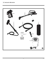
General view of application

2.1 

Application

All painting jobs in the workshop and on the building site, small 

dispersion work with the spray gun or inter nally fed Airless roller.

Examples of objects of spraying
Doors, door frames, balustrades, furniture, wooden cladding, fences 

radiators (heating) and steel parts, internal ceilings and walls.

2.2 

Coating materials

Processible coating materials

i

Pay attention to the  Airless quality of the coating 

materials to be processed.

Dilutable lacquers and paints or those containing solvents, two-

component coating materials, dispersions, latex paints.
No other materials should be used for spraying without 

WAGNER’

approval.

Filtering
Despite suction filter and insertion filter in the spray gun, filtering of 

the coating material is generally advisable.
Stir coating material before commencement of work.

i

Attention: Make sure, when stirring up with motor-

driven agitators that no air bubbles are stirred in. Air 

bubbles disturb when spraying and can, in fact, lead 

to interruption of operation.

Viscosity
With this unit it is possible to process highly viscous coating materials 

of up to around 20.000 MPa·s.
If highly viscous coating materials cannot be taken in by suction, they 

must be diluted in accordance with the  manufacturer’s instructions.

Two-component coating material
The appropriate processing time must be adhered to exactly. Within 

this time rinse through and clean the unit meticulously with the 

appropriate cleaning materials.

Coating materials with sharp-edged additional materials
These have a strong wear and tear effect on valves, high-pressure 

hose, spray gun and tip. The durability of these parts cane be reduced 

appreciably through this.

3. 

Description of unit

3.1 

Airless process

The main areas of application are thick layers of highly viscous 

coating material for large areas and a high consumption of material.
A piston pump takes in the coating material by suction and conveys it 

to the tip. Pressed through the tip at a pressure of up to a maximum 

of 214 bar (21.4 MPa), the coating material is atomised. This high 

pressure has the effect of micro fine atomisation of the coating 

material.
As no air is used in this process, it is described as an AIRLESS process.
This method of spraying has the advantages of finest atomisation, 

cloudless operation and a smooth, bubble-free surface. As well as 

these, the advantages of the speed of  work and convenience must 

be mentioned.

3.2 

Functioning of the unit

In the following there is a short description of the technical 

construction for better understanding of the function.
Wagner P20 units are electrically driven high-pressure spraying units.
A gear unit transfers the driving force to a crankshaft. The crankshaft 

moves the pistons of the material feed pump up and down. 
The inlet valve is opened automatically by the upwards movement 

of the piston. The outlet valve is opened when the piston moves 

downward.
The coating material flows under high pressure through the high-

pressure hose to the spray gun. When the coating material exits from 

the tip it atomizes.

The pressure control knob controls the volume and the operating 

pressure of the coating material.

Summary of Contents for P20 0552488

Page 1: ...Edition 8 2012 0552 874B GB Operating manual Models 0552488 0552490 P20 Airless high pressure spraying unit...

Page 2: ...doctor about the coating material or solvent used The operating instructions state that the following points must always be observed before starting up 1 Faulty units must not be used 2 Secure WAGNER...

Page 3: ...10 7 Interruption of work 10 8 Cleaning the unit shutting down 10 8 1 Cleaning unit from outside 10 8 2 Suction filter 11 8 3 Cleaning Airless spray gun 11 Page 9 Remedy in case of faults 12 10 Servic...

Page 4: ...d in place All accessories must be rated at or above the maximum operating pressure range of the sprayer This includes spray tips guns extensions and hose NOTE TO PHYSICIAN Injection into the skin is...

Page 5: ...ay hoses are routed in such a manner to minimize slip trip and fall hazard Clean up all material and solvent spills immediately to prevent slip hazard ALWAYS follow the material manufacturer s instruc...

Page 6: ...d in Air bubbles disturb when spraying and can in fact lead to interruption of operation Viscosity With this unit it is possible to process highly viscous coating materials of up to around 20 000 MPa...

Page 7: ...Return hose 4 Suction hose 5 Frame 6 Drip cup 7 Power cord 8 Relief valve Lever position vertical PRIME k circulation Lever position horizontal SPRAY p 9 Pressure control knob 10 ON OFF switch 11 Circ...

Page 8: ...Fig 2 Item 4 3 Screw the spray gun 5 with the selected tip onto the high pressure hose 4 Tighten the union nuts at the high pressure hoses firmly so that coating material does not leak 5 1 4 2 3 5 Fil...

Page 9: ...rd Do not spray without the tip guard in place NEVER trigger the gun unless the tip is completely turned to either the spray or the unclog position ALWAYS engage the gun trigger lock before removing r...

Page 10: ...tion without problems After you have finished spraying clean the unit Under no circumstances may any remaining coating material dry and harden in the unit The cleaning agent used for cleaning only wit...

Page 11: ...an appropriate cleaning agent 2 Clean tip thoroughly with appropriate cleaning agent so that no coating material residue remains 3 Thoroughly clean the outside of the Airless spray gun Intake filter i...

Page 12: ...ng material which is to be sprayed 2 Pressure setting incorrect 3 Volume too low 4 Coating material viscosity too high 1 Pressure setting too low Measures for eliminating the malfunction 1 Check volta...

Page 13: ...repair work Unplug the power plug from the outlet 11 1 Relief valve 1 Use a drift punch of 2 mm to remove the grooved pin Fig 8 Item 1 from the relief valve handle 2 2 Remove the relief valve handle 2...

Page 14: ...and O ring 6 9 Clean all the parts with the corresponding cleaning agent Check the inlet valve housing 1 inlet valve seat 5 and inlet valve ball 4 for wear and replace the parts if necessary If the wo...

Page 15: ...tighten by hand 13 Push installation tool included with the replacement packings for the piston 3 from above onto the piston 14 Lubricate installation tool and piston 3 with machine grease 15 Guide p...

Page 16: ...m MB FB MB FB M F M F M F F F F F F 1 2 3 4 M F F WH6WH1 WH2 WH7 WH4 WH5 Red Red Blue Blue Brown black Blue white Brown black Blue white Motor EMI filter Microswitch Power cord Switch Capacitors Black...

Page 17: ...elief valve handle fully counterclockwise k Circulation 2 Switch off the gasoline engine 3 Dismount the tip from the spray gun 4 Place tip in an appropriate cleaning agent until all coating material r...

Page 18: ...8 295 0552 619 719 70 0 019 0 48 320 0552 719 819 80 0 019 0 48 400 0552 819 Mica paints 221 20 0 021 0 53 145 0552 221 Zinc dust paints 421 40 0 021 0 53 190 0552 421 Dispersions 521 50 0 021 0 53 24...

Page 19: ...0m Spraypack consisting of basic unit 2311659 Airless gun AG 14 NPS 1 4 incl Trade Tip 2 nozzler holder F thread and Trade Tip 2 Fine Finish 410 2311660 2311853 TempSpray H 226 ideal for dispersions m...

Page 20: ...20 P20 g Accessories illustration 3 1 5 7 9 2 4 6 8...

Page 21: ...ssure hoses 1 4 x 1 4 6 0034 950 Metex Reuse Reuse for pre filtering of coating material in vessel Place suction pipe in the reuse 0034 952 Sieve package 5 pcs for paint 0034 951 Sieve package 5 pcs f...

Page 22: ...29 1 2 20 21 24 23 22 25 26 27 28 13 14 15 16 17 18 19 6 3 4 10 11 12 5 8 3 32 34 35 36 38 37 33 31 4 9 7 g Main Assembly 0558 466 110V 20 Ft 800 741 120V 8 25 Ft BS4343 NEMA 5 15P 8 466 10V Ft 800 74...

Page 23: ...522 Knob housing 16 9822 522 Retaining ring 17 02712 Spring 18 0551 521 Plunger 19 Drive assembly 20 0509 218 Screw 4 21 0551 518 Face plate 22 0552 482A Fluid section assembly 23 0507 931 Cam base 2...

Page 24: ...24 P20 Spare parts list P20 24 25 26 1 2 3 4 5 7 6 8 11 9 12 14 13 15 16 17 18 19 20 21 22 23 10 g Fluid section...

Page 25: ...2 Upper cage 13 0551 263 Crush washer 14 0508 672 Outlet valve ball 15 0551 620 Outlet valve seat 16 13481 Outlet valve retainer 17 704 535 Bushing 18 0509 581 Inlet valve seal 19 0509 591 Lower ball...

Page 26: ...Description 1 806 100A Housing assembly includes item 9 2 0508 573 Thrust washer 3 0508 572 Gear crankshaft assembly 4 0509 121 2nd stage gear 5 0558 353A Motor assembly 6 9820 213 Washer 4 7 9800 341...

Page 27: ...5 g Motor Assembly Item Part No g Description 1 0522 100 Capacitor assembly 2 806 304 Fan shroud 2 3 704 322 Screw 2 4 806 308 Fan 5 9804 916 Screw 6 0551 543 Tie wrap 7 0558 353A Motor assembly incl...

Page 28: ...377 Cord holder 2 806 071 Leg left 3 9885 546 Plug 2 4 0551 527 Screw 5 0509 856 Nut 6 0290 234 Leg right 7 806 216 Tube clip 8 0551 434 Screw 9 0508 381 Drip cup 10 9805 230 Screw 11 9885 546 Plug 2...

Page 29: ...arts list P20 g Suction system Item Part No g Description 1 0551 706 Siphon hose 2 9850 638 Tie wrap 2 3 0551 707 Retun tube 4 0279 459 Clip 5 9871 105 O ring 2 6 9822 526 Clip 0551 705 Siphon tube as...

Page 30: ...lgora MB Italia Tel 39 039 625 021 Telefax 39 039 685 18 00 info wagnercolora com CH Wagner International AG Industriestrasse 22 9450 Altst tten Schweiz Tel 41 71 7 57 22 11 Telefax 41 71 7 57 22 22 w...

Page 31: ...duct is not to be disposed of together with household waste material but must be recycled in an environmentally friendly way Wagner or one of our dealers will take back your used Wagner waste electric...

Page 32: ...claims must be made immediately or at the latest within a period of 2 weeks The authorised specialist shop that delivered the device is entitled to accept guarantee claims Guarantee claims may also b...

Reviews: