background image

5


OPERATING MANUAL

EDITION 05/2015

ORDER NUMBER DOC2319150

Table of Contents

TROUBLESHOOTING AND RECTIFICATION 

61

10 REPAIR 

WORK 

63

10.1 Repair 

Staff  

63

10.2 Safety 

Instructions 

63

10.3 Spray 

Gun 

64

10.3.1 Tools 

64

10.3.2  Disassembly of the Spray Gun 

65

10.3.3  Cleaning the Parts After Disassembly 

69

10.3.4  Assembling the Spray Gun 

70

11 

FUNCTIONAL CHECK AFTER REPAIR 

76

11.1 

Checking the High-voltage 

76

11.2 Air 

Test 

78

11.3 Product 

Pressure 

Test 

78

11.4 

Test of Spray Pattern 

78

12 DISPOSAL 

79

13 ACCESSORIES 

80

13.1 

Round Spray Nozzles 

80

13.1.1  ACR 5000 Round Jet Nozzle Cap 

80

13.1.2  AirCoat Round Jet Nozzle Inserts 

80

13.2 

Flat Jet Nozzles 

80

13.2.1  ACF 5000 Air Caps (Flat Jet) 

80

13.2.2  ACF5000 AirCoat Flat Jet Nozzles 

81

13.3 Filter 

83

13.4 

Hoses and Electric Cables 

84

13.4.1  Standard Hose Sets and Components 

84

13.4.2  Hose Sets for Low-resistance Products 

86

13.4.3  Product Hose 1.5 mm 

88

13.4.4  Gun Cables and Gun Cable Extensions 

88

13.5 Miscellaneous 

89

14 SPARE 

PARTS 

91

14.1 

How Can Spare Parts Be Ordered? 

91

14.2 

GM 5000EAC Spray Gun 

92

14.2.1  GM 5000EAC Adapter 

94

14.2.2  GM 5000EAC Handle 

96

14.3 

Accessories Spare Parts Lists 

98

14.3.1  Fan Spray Nozzles 

98

14.3.2  ACR 5000 Round Jet Nozzle Cap 

99

15 

WARRANTY AND CONFORMITY DECLARATIONS 

100

15.1 

Important Notes Regarding Product Liability 

100

15.2 Warranty 

Claim 

100

15.3 

CE Declaration of Conformity 

101

15.4 

EC Type Examination Certifi cate  

102

15.5 

Notes on German Regulations and Guidelines 

105

Summary of Contents for GM 50000EAC

Page 1: ...B_03154 Electrostatic AirCoat Spray Gun for manual operation for flat or round jet nozzles Version 05 2015 Translation of the Original Operating Manual...

Page 2: ......

Page 3: ...ipment 14 4 1 2 Personnel Qualifications 14 4 1 3 Safe Work Environment 14 4 2 Safety Instructions for Staff 15 4 2 1 Safe Handling of WAGNER Spray Devices 15 4 2 2 Grounding the Device 16 4 2 3 Produ...

Page 4: ...ng Staff 38 7 2 Safety Instructions 38 7 2 1 Emergency Deactivation 39 7 2 2 General Rules for Making Adjustments to the Spray Gun 39 7 3 Work 40 7 3 1 Filling with Working Material 41 7 3 2 Checking...

Page 5: ...t Jet Nozzles 80 13 2 1 ACF 5000 Air Caps Flat Jet 80 13 2 2 ACF5000 AirCoat Flat Jet Nozzles 81 13 3 Filter 83 13 4 Hoses and Electric Cables 84 13 4 1 Standard Hose Sets and Components 84 13 4 2 Hos...

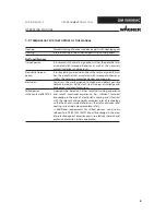
Page 6: ...tsconsequences DANGER This notice warns you of a hazard Possible consequences of not observing the warning instructions The signal word indicates the hazard level Themeasuresforpreventingthedangerandi...

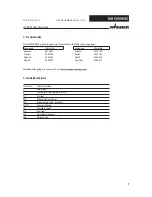
Page 7: ...rder No Language Order No German 2310481 English 2319150 French 2320152 Italian 2320153 Spanish 2320154 Dutch 2358832 Danish 2359979 Swedish 2360027 Additional languages on request or at Order No Orde...

Page 8: ...essary protective devices and measures Electrician Can assess the work assigned to him her and detect possible hazards based on his her technical training knowledge and experience in relevant provisio...

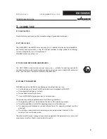
Page 9: ...e Chapter 3 Explosion Protection Identification WAGNER accepts no liability for any damage arising from incorrect use Use the device only to work with the products recommended by WAGNER Only operate t...

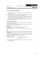
Page 10: ...do not directly measure the specific paint resistance Multiplying the result of the measurement with the device specific cell constant K we obtain the specific resistance value of the product Example...

Page 11: ...e defined working area Lacquering outside the defined working area Inhalation of substances hazardous to health Observe work and operation instructions Operation maintenance The forms of misuse listed...

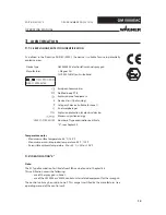
Page 12: ...n Switzerland SIRA 11 ATEX5374X European Communities Notified body PTB Explosion proof equipment Device class II not mining Category 2 device suitable for zone 1 Ex atmosphere gas Explosion protection...

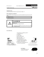
Page 13: ...ing injured by high pressure jet 2 Device type 3 Article number 4 Maximum high voltage 5 Maximum current 6 Maximum product pressure 7 Maximum air pressure 8 Do not dispose of used electrical equipment...

Page 14: ...measured insulation resistance must not exceed 100 megohms Paint mist extraction systems ventilation systems must be fitted on site according to local regulations Ensure that the following components...

Page 15: ...n devices ZH 1 406 and BGR 500 Part 2 Chapter 2 29 and 2 36 For shut down devices the examination can be suspended until the next start up Carry out the work steps as described in the Pressure Relief...

Page 16: ...oses may not be subjected to pressure Several liquids have a high expansion coefficient In some cases their volume can rise with consequent damage to pipes fittings etc and cause fluid leakage When th...

Page 17: ...used for cleaning and flushing agents The tanks must be grounded An explosive gas air mixture forms in closed tanks Never spray into a closed tank when using solvents for flushing External cleaning W...

Page 18: ...r of the lacquers solvents and cleaning agents being used Take the specified protective measures in particular wear safety goggles protective clothing and gloves as well as skin protection cream if ne...

Page 19: ...ay form electrostatic charges Flames or sparks can form during discharge Remove deposits from the surfaces to maintain conductivity Use only a damp cloth to clean the device Safe handling of WAGNER sp...

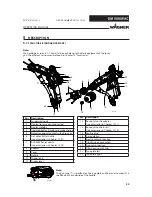
Page 20: ...er 13 2 2 8 Adapter 9 Cover 10 Handle 11 Trigger lock 12 Trigger lever Pos Description 13 Round jet nozzle adapter see accessories in Chapter 13 1 1 14 Round jet nozzle insert see accessories in Chapt...

Page 21: ...ously selected recipes numbers will be reloaded from the memory During spraying mode trigger lever pressed the status is shown in the display 2 by LEDs LED display Description LEDs 1 3 light up green...

Page 22: ...force needed to pull the trigger back will be perceived at the position where the product valve opens For spraying without high voltage the high voltage can be switched off using the operating button...

Page 23: ...gun basic version can be adapted optimally to any application depending upon the requirements and the desired accessories with the help of spray gun configuration The delivery note shows the exact sc...

Page 24: ...Output voltage maximum 80 kV DC Output current maximum 100 A DC Operating temperature range 0 C 40 C 32 F 104 F Maximum permissible product temperature 50 C 122 F Maximum surface temperature 85 C 185...

Page 25: ...applied High endurance of the nozzles Jet width adjustment In the AirCoat process the spray product is atomized under a pressure of 3 15 MPa 30 150 bar 435 2 176 psi With the help of an air pressure...

Page 26: ...ge electrode As a result the paint particles atomized by the spray gun are carried to the grounded work piece by kinetic and electrostatic energy where they adhere finely dispersed to the object to be...

Page 27: ...ed in closed rooms The air temperature at the storage location must be between 20 C and 60 C 4 F and 140 F The relative air humidity at the storage location must be between 10 and 95 without condensat...

Page 28: ...cable 4 Pneumatic pump 5 Sliding tables 6 Air pressure regulator air filter 7 Product suction system 8 Return hose 9 High pressure filter Description 10 Compressed air connection 11 Stop valve 12 Air...

Page 29: ...fety regulations for the additionally required system components WARNING Toxic and or flammable vapor mixtures Risk of poisoning and burns Operate the device in a spray booth approved for the working...

Page 30: ...30 OPERATING MANUAL EDITION 05 2015 ORDER NUMBER DOC2319150...

Page 31: ...the spraying quality and spraying pattern Bursting hose bursting threaded joints Danger to life from injection of product Ensure that the hose material is chemically resistant to the sprayed products...

Page 32: ...st if grounding is insufficient Danger of poisoning Insufficient paint application quality Ground all device components Ground the work pieces to be coated WARNING A poorly grounded work piece causes...

Page 33: ...unding scheme example Conveyor Mains cable Minimum cable cross section Control unit 4 mm2 AWG 12 Product supply Paint tank Conveyor 16 mm2 AWG 6 Booth Spraying stand Grounding of spray gun The spray g...

Page 34: ...ocess the different viscosities of the lacquer are optimally covered by two air cap types These can be found in Accessories In the case of application problems contact the paint producer mPa s 10 10 0...

Page 35: ...eck the permissible pressures for all the system components Check the level of the separating agent in the WAGNER pneumatic pump and fill the separating agent up if necessary Provide product tank tank...

Page 36: ...tion gun cable to control unit Secure the cover sleeve with the warning sign by means of the screw 84 on the connector The following points must be noted The cable connection to the gun and the connec...

Page 37: ...e maximum power is available with the standard cable length of 10 m An extension to a total length of up to 40 m will cause a power loss of up to 10 The gun cable can be extended to a total length of...

Page 38: ...ms WARNING Observe safety instructions in Chapter 4 Incorrect operation Risk of injury and damage to the device The operating staff must be qualified and fit to operate the entire system The operating...

Page 39: ...Danger to life from injecting paint or solvent Never reach into the spray jet Never point the spray gun at people Consult a doctor immediately in the event of skin injuries caused by paint or solvent...

Page 40: ...5 9 17 1 2 16 15 14 21 12 11 10 B_03158 18 19 20 3 3 13 OPERATING MANUAL EDITION 05 2015 ORDER NUMBER DOC2319150 7 3 WORK Ensure that the regular safety checks are carried out in accordance with Chapt...

Page 41: ...e an optimum spray pattern See below Spray pattern and air regulation Repeat points 6 and 7 until the optimum spray pattern is reached iterative process 1 Place empty tank 18 under return tube 8 2 Pla...

Page 42: ...t being sprayed The illustration shows the influence of the regulator on the spraying pattern Other nozzle sizes can be used to obtain larger or smaller spraying patterns Changing the Flow Rate Adapt...

Page 43: ...pray gun does not affect the spray pattern in this process Flow rate 9 Product quantity may be able to be reduced by Minimizing the product pressure Use a different nozzle see Chapter 13 1 Secure gun...

Page 44: ...aint or solvent Never reach into the spray jet Never point the spray gun at people Consult a doctor immediately in the event of skin injuries caused by paint or solvent Inform the doctor about the pai...

Page 45: ...1 by a half turn 2 Remove the nozzle spanner and briefly actuate trigger 3 After flushing the nozzle re tighten the nozzle insert 7 3 6 REPLACING ROUND JET NOZZLE S NOZZLE INSERT Exploding gas air mix...

Page 46: ...using 12 Put the air cap 10 on the nozzle 11 and pay attention to the position of the guide surfaces 13 Screw union nut with attached nozzle guard 9 to the gun body and make sure that the air cap horn...

Page 47: ...47 B_03162 1 2 3 4 5 6 7 8 10 9 Y 11 1 OPERATING MANUAL EDITION 05 2015 ORDER NUMBER DOC2319150...

Page 48: ...aces of paint have been removed Defective AirCoat nozzle Insufficient paint application quality Do not use sharp edged objects to treat carbide on the AirCoat nozzle NOTICE 6 Insert new ACF5000 nozzle...

Page 49: ...henozzlescrewconnection 7 can be placed in a cleaning solvent recommended by the lacquer manufacturer All other nozzle parts may not be put into cleaning solvent Clean these parts with a cleaning solv...

Page 50: ...n 9 Turn the trigger lock 14 to the spraying position and briefly pull the trigger 10 When the blockage has been flushed out secure the gun with trigger lock 14 11 Relieve pressure Chapter 7 3 4 12 Un...

Page 51: ...51 B_04388 10 11 X Y 1 14 Y 9 12 12 OPERATING MANUAL EDITION 05 2015 ORDER NUMBER DOC2319150 ACF5000 nozzle in cleaning position ACF5000 nozzle in spray position...

Page 52: ...ng Damage to the device Activate the spray gun trigger when changing the valve housing NOTICE To prevent damage to the gun valve seat rubs on the valve needle valve needle may loosen activate the spra...

Page 53: ...53 OPERATING MANUAL EDITION 05 2015 ORDER NUMBER DOC2319150...

Page 54: ...8 1 1 CLEANING STAFF Observe safety instructions in Chapter 4 DANGER Incorrect maintenance repair Danger to life and equipment damage Only a WAGNER service center or a suitably trained person may car...

Page 55: ...ay gun have to be cleaned and which product has to be removed When cleaning the spray gun only use non polar cleaning agents to prevent conductive residues on the surface of the spray gun Should it ho...

Page 56: ...the compatibility of the cleaning and flushing agents and working media on the basis of the safety data sheets WARNING Damage to electrical devices Never immerse the spray gun in cleaning agent NOTIC...

Page 57: ...9 Remove flushing agent supply With flat jet nozzle fitted 5 Dismount AirCoat nozzle and clean separately Chapter 7 3 8 6 Point the spray gun toward the collecting tray and actuate the trigger 7 Flush...

Page 58: ...cked for being in a reliable state after maintenance work is completed 8 2 1 MAINTENANCE STAFF 8 2 2 SAFETY INSTRUCTIONS Observe the safety instructions in Chapter 4 and Chapter 8 1 2 Prior to mainten...

Page 59: ...all times when carrying out work For the safe operation of electrostatic manual coating systems for flammable liquid coating products intervals for periodical inspections are defined as follows Inspe...

Page 60: ...device is reduced due to environmental influences even when handled correctly Check hoses pipes and couplings every day and replace if necessary Before every commissioning check all connections for le...

Page 61: ...ance too high too low Check paint resistance see Chapter 2 5 Spraying pressure too high Readjust spraying pressure No wrap around No high voltage Switch on high voltage at the control unit Repair malf...

Page 62: ...62 OPERATING MANUAL EDITION 05 2015 ORDER NUMBER DOC2319150...

Page 63: ...and check for leaks Chapter 11 3 Function test in accordance with Chapter 11 In accordance with the guideline for liquid ejection devices ZH 1 406 and BGR 500 Part 2 Chapter 2 29 and Chapter 2 36 The...

Page 64: ...end wrench SW14 Open end wrench SW19 Open end wrench SW21 Open end wrench SW22 Ring spanner SW9 Ring spanner SW11 Torx wrench 20 Torx wrench 25 Slide gauge Valve needle assembly tool Order No 2309368...

Page 65: ...Torx 25 1 2 3 B_03194 SW3 SW12 SW12 OPERATING MANUAL EDITION 05 2015 ORDER NUMBER DOC2319150 10 3 2 DISASSEMBLY OF THE SPRAY GUN Air hose When unscrewing the air hose a second open ended box wrench m...

Page 66: ...ute slight rotational movements Fitting 25 If the fitting 25 does not come out with the product hose it must be removed from the gun adapter as follows Screwthewoodscrew 3mm 0 12inches length40mm 1 6i...

Page 67: ...ssembly tool or socket or ring spanner no open end wrench O ring 8 1 Use screwdriver no 1 to press under the O ring 2 Lever up the O ring and remove it Air distribution 9 1 Locate the start of the thr...

Page 68: ...ired Remove rod seal 10 Do not damage the housing in the process Two gold contact sleeves either remain in the handle 1 or are seated on the two gold pins 2 Do not lose 1 Loosen the oval head screw 3...

Page 69: ...ease note All reusable parts except for the parts conducting high voltage such as cascade adapter plug compl etc should be cleaned thoroughly using a suitable cleaning agent The adapter connector insi...

Page 70: ...ringly sparingly Ensure the correct insertion position Ensure the correct insertion position Only as required if the seal was removed press in using handle seal assembly tool Order No 2342334 not incl...

Page 71: ...in 6 using an Allen key SW2 Coat the hollow section with a brush Note Avoid the pin and hexagon sparingly Wear gloves The outside thread of the packing 9 must be free of lacquer Valve rod unit 8 and p...

Page 72: ...3 fingers using an assembly tool 3 Use assembly tool socket or ring spanner no open end wrench to tighten the valve housing 3 4 Slide the valve rod to the forward position at the valve seat 4 Valve ne...

Page 73: ...the inside of the adapter and the cascade then grease the cascade surface with Vaseline Fitting 25 Before assembling the product hose check that no fitting 25 is in the gun adapter Check the fitting f...

Page 74: ...ocess only exert counter pressure on the sleeve bracket and not on the entire cover 2 Position cover straight and level and carefully press in Use only minimal force gently rocking from side to side i...

Page 75: ...9150 Flat jet nozzle Assembly see Chapter 14 3 1 Diverse nozzle sizes see Chapter 13 2 Round jet nozzle Assembly see Chapter 14 3 2 Diverse nozzle sizes see Chapter 13 1 Air hose When screwing on the...

Page 76: ...cked with the display on the control unit VM 5000 Note The gun must be clean and dry and must not have any paint or cleaning agent residues In the case of ambient air with a high air humidity the meas...

Page 77: ...2015 ORDER NUMBER DOC2319150 Disruptive discharge test Check the gun against ground with the grounding rod No sparks should be formed Note in the vicinity of the electrode harmless corona discharges c...

Page 78: ...ration Connect high pressure hose to the spray gun Test the seal of the spray gun with suitable medium e g flushing agent or Marcol 52 and a maximum pressure of 25 MPa 250 bar 3 626 psi Increase the p...

Page 79: ...th the household refuse but must be recycled in an environmentally correct manner WAGNER or one of our dealers will take back your used WAGNER electric or electronic equipment and will dispose of it f...

Page 80: ...Recommended gun filter mm inch 132720 11 approx 250 10 red 132721 12 approx 250 10 200 meshes 132722 13 approx 250 10 132723 14 approx 250 10 132724 15 approx 250 10 132725 16 approx 250 10 yellow 132...

Page 81: ...0 011 10 Synthetic resin lacquer 395211 11 20 20 PVC lacquer 395311 11 30 30 395411 11 40 40 395511 11 50 50 395611 11 60 60 395811 11 80 80 395113 13 10 0 33 0 013 10 Lacquers 395213 13 20 20 Base co...

Page 82: ...0 021 20 Mica paints 395421 21 40 40 Zinc rich paints 395521 21 50 50 Rust proofing paints 395621 21 60 60 Glue paints 395821 21 80 80 395423 23 40 0 58 0 023 40 395623 23 60 60 395823 23 80 80 395425...

Page 83: ...B_00019 OPERATING MANUAL EDITION 05 2015 ORDER NUMBER DOC2319150 13 3 FILTER Order No Designation 3204604 Edge filter 60 mesh white 3204605 Edge filter 100 mesh black 9999002 Edge filter 200 mesh yell...

Page 84: ...0 5 m 3676437 Protection hose fabric PP30 10 5 m Pos Stk Order No Designation 1 1 2339173 Hose set GM 5000EAC 15 0 m Consists of 2 1 9984573 15 High pressure hose DN4 PN270 NPS 15 0 m PA 3 1 2339154 A...

Page 85: ...0 2339174 Hose set GM 5000EAC 20 m 29 2 65 2 300 10 20 10 1 500 100 Notes Melt the hose ends at both sides gun pump and turn approx 5 cm of each hose end to the inside Fix the protective hose with cab...

Page 86: ...bric PP30 10 5 m Pos Stk Order No Designation 1 1 2339181 Hose set GM 5000EAC 15 0 m Low R Consists of 2 1 2310470 High pressure product hose EAC complete 15 0 m Low R inclusive pos 6 3 1 2339154 Air...

Page 87: ...set GM 5000EAC 15 m Low R 206 2 177 2 300 10 20 10 1 500 100 188 1 2339182 Hose set GM 5000EAC 20 m Low R 206 2 177 2 300 10 20 10 1 500 100 188 1 Notes Melt the hose ends at both sides gun pump and...

Page 88: ...49 2 ft 20 m 65 6 ft 25 m 82 0 ft 32 m 105 ft 62 m 203 ft Order No 2339157 2339158 2339159 2339160 2344995 2344996 GM 5000E extension cable Max total length of 80 m 262 ft see Chapter 6 6 3 1 Length...

Page 89: ...015 ORDER NUMBER DOC2319150 Order No Designation 2319653 Protective gun coating 259010 High voltage tester HV 200 N 2326041 Paint resistance meter 999080 Wet film thickness gauge 50342 Viscosity cup D...

Page 90: ...ANUAL EDITION 05 2015 ORDER NUMBER DOC2319150 128901 Nozzle spanner ACR 2325263 Clamping screw assembly tool 2326485 Wall mount GM 5000E left right 2324766 Swivel joint air 2327060 Fitting SJM GM5000E...

Page 91: ...express delivery air freight courier etc Identification in spare parts lists Explanation of column K labeling in the following spare parts lists Wearing parts Note These parts are not covered by warra...

Page 92: ...92 B_03153 19 20 21 7 5 8 9 10 12 11 13 14 15 18 16 17 6 22 1 25 24 OPERATING MANUAL EDITION 05 2015 ORDER NUMBER DOC2319150 14 2 GM 5000EAC SPRAY GUN Dismantling and assembly See Chapter 10...

Page 93: ...exagon socket cylinder head screw 11 1 2311970 Sealing plug 12 1 2307104 Screw plug 13 1 2312180 Air regulation complete including item 14 14 1 9971182 O ring 15 1 9971182 O ring 16 1 2314360 Trigger...

Page 94: ...04368 5 1 15 13 12 11 6 4 10 21 22 14 24 123 0 1 mm 4 8425 0 004 inch 2 3 25 9 8 7 OPERATING MANUAL EDITION 05 2015 ORDER NUMBER DOC2319150 14 2 1 GM 5000EAC ADAPTER Dismantling and assembly See Chapt...

Page 95: ...1 2314283 Contacting AC 8 1 9952777 High resistance bare 9 1 9960808 Socket contact component gold contact sleeve 10 1 2312181 Cascade complete 11 1 9974166 O ring 12 1 2307062 Clamping screw valve ro...

Page 96: ...96 7 1 B_04775 8 9 10 12 5 6 3 2 4 23 11 18 13 24 25 26 OPERATING MANUAL EDITION 05 2015 ORDER NUMBER DOC2319150 14 2 2 GM 5000EAC HANDLE Dismantling and assembly See Chapter 10...

Page 97: ...2307232 Adapter seal 8 1 2311952 Stop screw 9 1 2309825 Oval head screw with hexagon 10 1 2310692 Gasket 11 1 2311182 Parallel pin 12 1 2309400 Safety clip 13 1 2312189 Air valve 18 1 9974218 O ring...

Page 98: ...3 1 FAN SPRAY NOZZLES Flat jet nozzles spare parts list Pos K Stk Order No Designation 1 1 2315775 Union nut AC complete 2 1 2309882 Air cap ACF 5000 LV red 2 1 2314203 Air cap ACF 5000 HV blue 3 1 23...

Page 99: ...parts list Pos K Stk Order No Designation 1 1 2309883 Round jet nozzle cap ACR 5000 2 1 2307220 Nozzle nut 3 1 2315310 O ring 4 1 132351 Nozzle screwed connection holder 5 1 2307219 Nozzle body 6 1 2...

Page 100: ...an the address of the purchaser We do not provide warranty for damage that has been caused or contributed to for the following reasons Unsuitable or improper use faulty assembly or commissioning by th...

Page 101: ...61000 6 2 2006 DIN EN ISO 12100 2011 DIN EN 1953 2010 DIN EN 61000 6 4 2011 DIN EN 60079 0 2010 DIN EN 60079 15 2011 DIN EN 60204 1 2007 Applied national technical standards and specifications in part...

Page 102: ...102 OPERATING MANUAL EDITION 05 2015 ORDER NUMBER DOC2319150 15 4 EC TYPE EXAMINATION CERTIFICATE...

Page 103: ...103 OPERATING MANUAL EDITION 05 2015 ORDER NUMBER DOC2319150...

Page 104: ...104 OPERATING MANUAL EDITION 05 2015 ORDER NUMBER DOC2319150...

Page 105: ...ith Liquid Ejection Devices Part 2 Chapter 2 29 Working with Coating Products Avoiding ignition risks Equipment for cleaning work pieces with solvents Guidelines for liquid ejection devices Painting r...

Page 106: ...106 OPERATING MANUAL EDITION 05 2015 ORDER NUMBER DOC2319150...

Page 107: ......

Page 108: ...2319150 Edition 05 2015 Germany Phone Telefax E mail Switzerland Phone Telefax More contact addresses on the internet at Company Locations WAGNER worldwide Subject to changes without notice Document...

Reviews: