17
GA 2800EA, GA 2805EA
%
'
(
)
&
!
"
#
,
-
+
$
$
'
*
(
'!%!
'!%!
"?
OPERATING MANUAL
EDITION 12/2008
PART NO. DOC350731
4.4.1
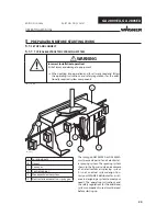
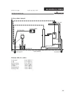
DESIGN OF SPRAY GUN
4.4.2
FUNCTIONS OF THE GUN
Note
Operation of the spray gun in conjunction with the control unit EPG 3000 is described in this operating man-
ual.
➞
The high voltage at the spray gun GA 2800EA or GA 2805EA is activated when the control unit EPG 3000 is
switched on.
➞
The control piston integrated on the valve rod in housing (B) of the spray gun GA 2800EA or GA 2805EA is
subjected to pressure at the same time and opens the air valve for the atomizing air.
➞
Paint valve in the gun barrel (F) is opened via valve rod movement after the valve for the atomizing air is
opened.
➞
The spray jet width is adjusted via the air control knob on the control unit EPG 3000 or via the fan air
regulation (D1) on the spray gun GA 2800EA in the case of fl at jet spraying.
➞
The high voltage at the spray gun can be adjusted at the voltage regulator in the control unit EPG 3000 and
can be adapted to the paint or to the spraying object.
➞
Securing the gun:
1. Switch off the mains at the EPG 3000
2. Switch off the air supply at the EPG 3000
3. Relieve the pressure on the spray gun and the system.
A
Tension nut for valve rod
G2
Air cap fl at jet
B
Housing
H
Nozzle
C
Cascade
I
Control air connection (red)
D1
Fan air regulation GA 2800EA
J
Atomizing air connection (blue)
D2
Fan air connection GA 2805EA
K
Gun holder
E
Head piece
L
Paint hose connection
F
Gun barrel
M
Connection to control unit
G1
Nozzle nut round jet
N
Protection cap
4.4
FUNCTION


