EN
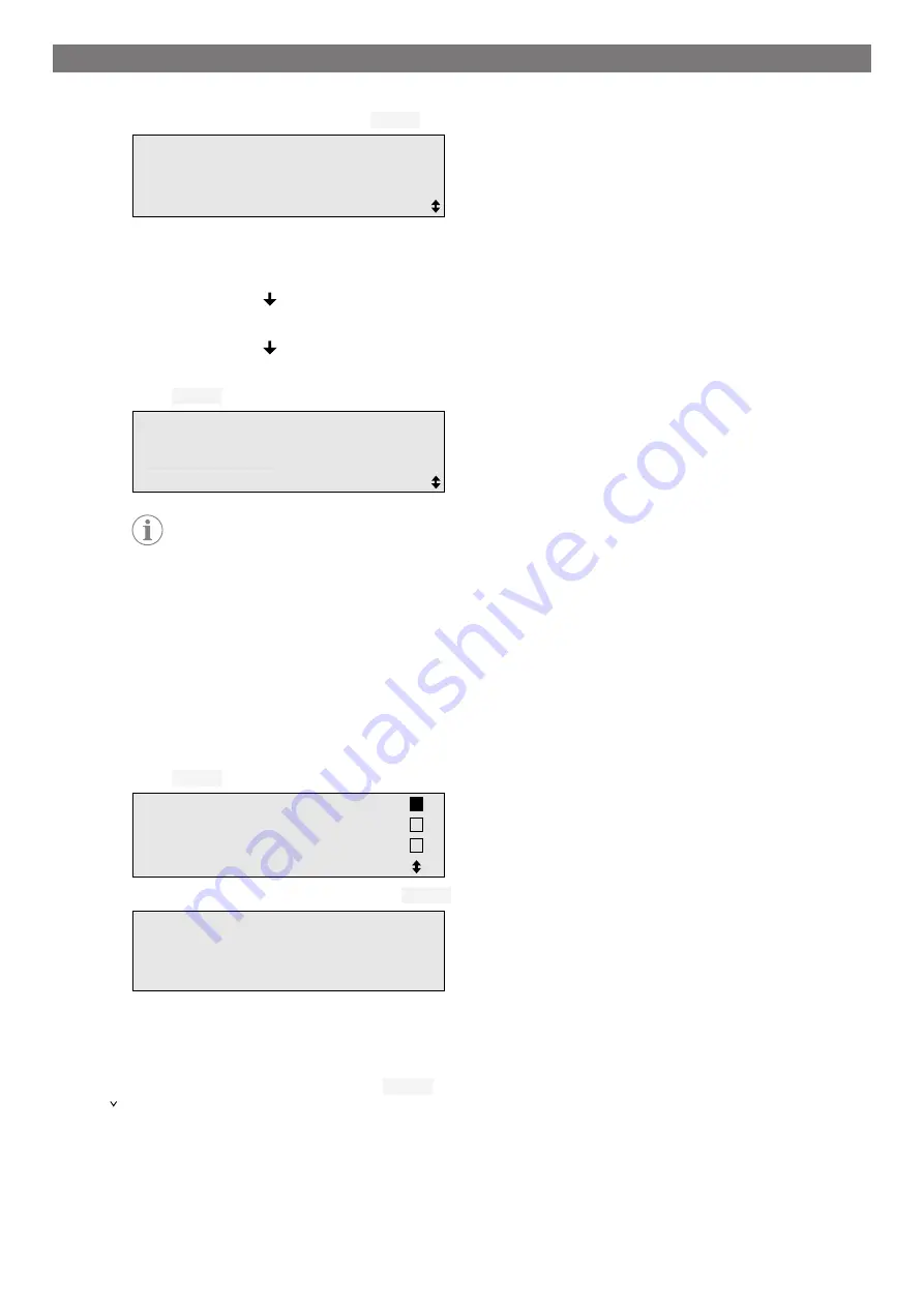
13.8.3 Filling process
1.
Enter the preferred settings and press
ENTER
to confirm.
Filling phase?
Yes
No
ENTER-OK STOP-EXIT
2.
If
Filling phase
has been selected, enter the required value, otherwise continue with chapter
on page 26.
3.
Enter the amount of refrigerant oil which was previously drained or which is required.
4.
Press the cursor key .
5.
Enter the additive quantity.
6.
Press the cursor key .
7.
Enter the refrigerant quantity.
8.
Press
ENTER
to confirm all settings.
PAG oil
ml.
0
UV tracer
ml.
7
Refrigerant
g.
500
ENTER-OK STOP-EXIT
Note
•
If extraction is taking place in the same process sequence, the quantity of fresh oil is counted as an
additional filling quantity, and is added to the drained oil quantity extracted beforehand. If this value
is set to 0, exactly the quantity of oil which was extracted will be filled again.
•
To add fresh oil or UV additive, a vacuum process must be performed in the same process se-
quence. If no vacuum process has been selected, only refrigerant can be selected in the filling
menu.
13.8.4 Selecting connections
1.
Select the parameters in accordance with the air conditioning system connections:
•
Air conditioning system has a high pressure and a low pressure connection: Select
LP/HP
.
•
Air conditioning system only has a high pressure connection: Select
HP
.
•
Air conditioning system only has a low pressure connection: Select
LP
.
2.
Press
ENTER
to confirm.
HP/LP
PORT
HP
PORT
LP
PORT
ENTER-OK STOP-EXIT
3.
Once all settings have been entered, press
ENTER
to start the process.
Process start?
ENTER-OK STOP-EXIT
13.8.5 After ending the air conditioning service
After the air conditioning service has finished, you are prompted to disconnect the hoses of the A/C service unit
from the vehicle air conditioning system.
1.
Disconnect the service hoses and press
ENTER
to confirm.
The service hoses will now be drained. the A/C service unit is then ready for further use.
2.
Screw the valve caps of the air conditioning system back on the connections.
26
Summary of Contents for 9103303105
Page 9: ...EN 16 USB port 9 ...
Page 41: ...EN 17 1 Flowchart ASC6300 G Legend 41 ...
Page 44: ...EN 17 2 Flowchart ASC6400 G Legend 44 ...
Page 47: ...EN 17 3 Circuit diagram ASC6300 G 47 ...
Page 48: ...EN 48 ...
Page 49: ...EN 17 4 Circuit diagram ASC6400 G 49 ...
Page 50: ...EN 50 ...
Page 58: ...FR 16 Port USB 58 ...
Page 92: ...FR 17 1 Organigramme ASC6300 G Légende 92 ...
Page 95: ...FR 17 2 Organigramme ASC6400 G Légende 95 ...
Page 98: ...FR 17 3 Schéma électrique ASC6300 G 98 ...
Page 99: ...FR 99 ...
Page 100: ...FR 17 4 Schéma électrique ASC6400 G 100 ...
Page 101: ...FR 101 ...
Page 109: ...DE 16 USB Anschluss 109 ...
Page 142: ...DE 17 1 Flussdiagramm ASC6300 G Legende 142 ...
Page 145: ...DE 17 2 Flussdiagramm ASC6400 G Legende 145 ...
Page 148: ...DE 17 3 Schaltplan ASC6300 G 148 ...
Page 149: ...DE 149 ...
Page 150: ...DE 17 4 Schaltplan ASC6400 G 150 ...
Page 151: ...DE 151 ...
Page 159: ...RU 16 USB порт 159 ...
Page 192: ...RU 17 1 Блок схема ASC6300 G Пояснения 192 ...
Page 195: ...RU 17 2 Блок схема ASC6400 G Пояснения 195 ...
Page 198: ...RU 17 3 Схема соединений ASC6300 G 198 ...
Page 199: ...RU 199 ...
Page 200: ...RU 17 4 Схема соединений ASC6400 G 200 ...
Page 201: ...RU 201 ...
Page 209: ...ES 16 Conexión USB 209 ...
Page 244: ...ES 17 1 Diagrama de flujo ASC6300 G Leyenda 244 ...
Page 247: ...ES 17 2 Diagrama de flujo ASC6400 G Leyenda 247 ...
Page 250: ...ES 17 3 Esquema de conexiones ASC6300 G 250 ...
Page 251: ...ES 251 ...
Page 252: ...ES 17 4 Esquema de conexiones ASC6400 G 252 ...
Page 253: ...ES 253 ...
Page 254: ...4445103554 2022 11 30 ...


