background image

Tables

Technical data

BA  RC50_RC70  en  00

177

Designation

Value

Unit

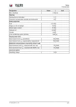
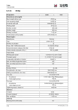
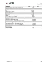
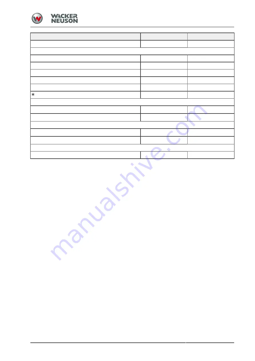
Pendulum compensation upwards and downwards

10 °

Filling capacities

Fuel

123.00 l

Engine oil (for oil change)

10.50 l

Diesel engine coolant

11.00 l

Hydraulic oil

60.00 l

Vibrator

10.00 l

 Air-conditioning system (R134a)

0.85 kg

Sound power level

Sound power level L

WA

, guaranteed

104 dB(A)

Sound power level L

WA

, representative measurement

102 dB(A)

Emissions sound pressure level at the driver's seat

Sound pressure level L

pA

, measured with cab, max.

79 dB(A)

Sound pressure level L

pA

, measured with ROPS, max.

87 dB(A)

Electrical system

Operating voltage

12 V

Summary of Contents for RC50

Page 1: ...Instruction manual Compactor RC50 RC70 Vehicle type RC50 RC70 Issue 00 Document order number 5100051060 Language en From serial number WNCR1201JHAA00160...

Page 2: ...nufactured for Wacker Neuson Produktion GmbH Co KG Wackerstra e 6 D 85084 Reichertshofen Germany www wackerneuson com Tel 49 0 8453 340 32 00 E mail service LE wackerneuson com Original instruction ma...

Page 3: ...BA RC50_RC70 en 00 3 This operating manual is valid for the following roller types COMPACTOR RC50 RC50p RC70 RC70p RC70vo...

Page 4: ...rning notes 15 1 01 Documentation 16 1 02 Use 17 1 02 01 Intended use 17 1 02 02 Abnormal use 17 1 02 03 Residual risks 18 1 02 04 Climatic conditions 18 1 03 Environmental protection 20 1 04 Disposal...

Page 5: ...ion 49 2 07 Steering system 50 2 08 Dynamic compaction system 51 3 Operation 52 3 00 Important information about operating the machine 52 3 01 Safety strut 54 3 02 Loading and transporting 56 3 03 Fun...

Page 6: ...ing with the dynamic compaction system 97 3 20 01 Switching the compaction system on and off 98 3 20 02 Jump operation RMV 99 3 20 03 Compaction HMV 100 3 21 Adjusting scrapers 101 3 22 Exhaust gas af...

Page 7: ...4 03 Drive unit diesel engine 134 4 03 01 Lubricating oil change intervals 135 4 03 02 Engine oil change for parked regeneration 135 4 03 03 Maintenance points on the diesel engine when changing oil...

Page 8: ...ng cylinder pins 156 4 08 Dynamic compaction system 158 4 08 01 Checking the damping elements 158 4 08 02 Checking the vibrator oil fill level 158 4 08 03 Changing the vibrator oil 159 5 Tables 160 5...

Page 9: ...nting Dismounting 189 6 02 04 Operation 191 6 02 05 Maintenance 192 6 03 Rear area monitoring 193 6 03 01 Overview 193 6 03 02 Description 193 6 03 03 Operation 193 6 04 Tachograph 195 6 04 01 Overvie...

Page 10: ...EC Declaration of Conformity 10 BA RC50_RC70 en 00 EC DECLARATION OF CONFORMITY...

Page 11: ...improper maintenance may present risks Please operate and maintain your Wacker Neuson machine as described in this instruction manual Doing so will ensure smooth operation and high system availability...

Page 12: ...ceived a quality product All the components of this machine have been carefully inspected and tested Therefore they comply with the quality that you expect The reliability of the machine is preserved...

Page 13: ...machine damaged After unpacking protect the machine from moisture and contamination if it is not going to be brought into operation immediately 1 00 06 Signs and symbols The signs and symbols used in...

Page 14: ...1 3 1 Driver 2 Engine compartment 3 Drive lever Descriptive text You use the drive lever 3 to determine the direction of travel and driving speed 1 00 07 Explanation of abbreviations Abbreviations are...

Page 15: ...nal word indicates the particular seriousness of the danger to persons and machines objects and the environment DANGER Indicates an immediate danger to persons If the danger is not averted death or th...

Page 16: ...instruction manual consists of Safety manual Instruction manual of the machine Instruction manual of the diesel engine If necessary additional information e g QR code This instruction manual must be k...

Page 17: ...use and or all machine related activities not described in this instruction manual is to be deemed as unauthorised misuse outside the legal limits of indemnity of the manufacturer 1 02 02 Abnormal us...

Page 18: ...ty instructions Operating instructions of the operator Danger of life risk of personal injury when operating the machine due to Misuse Improper operation Transport Missing protective equipment Defecti...

Page 19: ...ion depend on The fuel used The viscosity of the motor gear and hydraulic oil The battery s charge state Please note The acceleration and braking behaviour of the machine are influenced by viscous hyd...

Page 20: ...ging cleaning materials and used or residual operating materials for recycling Observe the environmental protection regulations applicable at the place of use N O T E When operating the machine observ...

Page 21: ...ocal regulations of the relevant country Materials metal plastics To be able to dispose materials professionally these materials need to be correctly sorted Cleanse materials of adhesive impurities Pl...

Page 22: ...s machine in the European Economic Area EEA in Switzerland and in Turkey is inadmissible N O T E For machines without EC Conformity neither an EC Declaration of Conformity nor a CE type plate can be i...

Page 23: ...g Regulations only valid for transport on public roads 11 Permissible axle load at the front rear in accordance with the StVZO German Road Traffic Licensing Regulations only valid for transport on pub...

Page 24: ...Preface Type plate 24 BA RC50_RC70 en 00...

Page 25: ...ied by a type plate that is attached to the cab roll over bar Control stand page 42 17237 8 7 2 1 4 3 6 5 1 Series type part of the VIN PIN 2 Cab ROPS identification number 1 3 Cab ROPS identification...

Page 26: ...is also indicated by a specially produced type plate It is located on the side of the machine type plate in the engine compartment 17390 7 2 1 4 3 6 5 1 Engine manufacturer 2 Type 3 Engine identificat...

Page 27: ...operator panel The sound intensity level on the driver s seat is specified in the machine s technical data see Technical data sqq measurement inaccuracy according to DIN EN ISO 11201 N O T E When wor...

Page 28: ...n case of trouble Please adhere to the following instructions Please drive the machine only if you are entirely familiarized with the operating and control elements and the method of operation Please...

Page 29: ...the following instructions Please make yourself familiar with the machine s and the loading vehicle s dimensions Wear reflective clothing For instructing please use voice radio e g when loading with a...

Page 30: ...the negative terminal ground strap at the battery ROPS FOPS protective structures The machine frame in way of the ROPS or and FOPS mounting may not be distorted bent or torn deformed The reinforcemen...

Page 31: ...corresponding vehicle owner only A corresponding driving licence is required for operating this vehicle on public roads The exemption may not be used unless an insurance cover is available Both the or...

Page 32: ...oading and transporting machines Inactive zone With the machine stationary and the diesel engine switched off the area 1 metre around the machine is defined as the danger zone Only operating personnel...

Page 33: ...oscillation Steering Hydrostatic assisted steering via 3 point pendulum articulated joint Large steering lock to both sides Pendulum compensation upwards and downwards Service brake During operation...

Page 34: ...ents here N O T E Auxiliary devices may change the sequence of action steps or events This is indicated by an additional note in the text for example For versions with an air conditioning system ROPS...

Page 35: ...eral view of machine 2 01 01 Chassis safety devices 10 8 9 5 4 3 7 1 2 3 1 11 6 1 Towing eyes for crane loading 2 Towing eye 3 Lashing point 4 Steering block 5 Steps 6 Engine hood 7 Chassis 8 VIN 9 Ma...

Page 36: ...on signs please refer to the spare parts catalogue N O T E Be sure to observe the warning signs and information signs affixed to the machine and strictly follow their instructions Information signs Be...

Page 37: ...N Drain outlet for engine oil M A R G I N Drain outlet for fuel filter water sump M A R G I N Coolant fill level M A R G I N Coolant filling inlet M A R G I N Tyre pressure Tyre without water filling...

Page 38: ...s The check and maintenance work that is to be carried out may deviate from what is shown depending on the model and equipment of the machine This is not an exhaustive representation of the activities...

Page 39: ...stem Sprinkler nozzles Drain the water sump on the water separator Functional check in the case of an existing ma chine Seat contact switch EMERGENCY STOP Safety switch for multifunction armrest Parki...

Page 40: ...rking spotlight 8 Seat console 9 Storage compartment for operating manual first aid kit 10 12 V socket 11 Steering column 12 Position for fire extinguisher 2 01 05 Cab 2 1 11 10 5 3 7 8 9 3 3 6 4 1 RO...

Page 41: ...Description General view of machine BA RC50_RC70 en 00 41 2 01 06 Consumable fill holes 1 1 Fuel...

Page 42: ...anel 4 Drive lever Cab roof section 9 10 9 4 4 8 7 6 5 4 4 2 1 2 3 1 Windscreen wiper switch unit 2 Interior lighting 3 Heating air conditioning system switch unit 4 Heating air conditioning system ve...

Page 43: ...weight 5 Armrest inclination adjustment 6 Armrest height adjustment 7 Backrest inclination adjustment 2 02 03 Steering column 1 9 7 8 6 5 4 2 3 1 Control panel 2 Steering wheel 3 Electrical system eng...

Page 44: ...signal horn switch 3 Work light 4 Rotating beacon 5 Parking brake 6 Hazard warning light 7 Dynamic compaction system 8 Info display for system info diagnostic codes 9 DPF regeneration switch 10 DPF in...

Page 45: ...tand BA RC50_RC70 en 00 45 Version with dozer blade 1 4 5 2 3 1 Floating position of dozer blade switch 2 Raise the dozer blade switch 3 Lower the dozer blade switch 4 Dynamic compaction system switch...

Page 46: ...iesel engine 8 3 4 5 6 2 1 7 9 10 11 1 Filling opening for engine oil 2 Dipstick 3 Cooling system 4 Fuel system 5 Diesel engine with drive units 6 Drain outlet for engine oil 7 Dust valve 8 Air filter...

Page 47: ...y BA RC50_RC70 en 00 47 2 04 Hydraulic oil supply 1 2 4 3 5 6 3 1 Hydraulic oil filling opening 2 Hydraulic oil tank ventilation filter 3 Hydraulic oil tank 4 Fill level indicator 5 Hydraulic oil filt...

Page 48: ...Description Electrical system 48 BA RC50_RC70 en 00 2 05 Electrical system 3 1 2 4 1 Battery 2 Main fuses 3 Fuses electrical box 4 Fuse alternator D...

Page 49: ...Description Transmission BA RC50_RC70 en 00 49 2 06 Transmission 1 2 2 1 1 Travel drive motor 2 Scraper...

Page 50: ...Description Steering system 50 BA RC50_RC70 en 00 2 07 Steering system 3 1 1 2 1 1 3 point pendulum articulated joint 2 Steering cylinder 3 Steering block...

Page 51: ...on Dynamic compaction system BA RC50_RC70 en 00 51 2 08 Dynamic compaction system 4 1 3 2 1 Drum with vibrator 2 Vibrator oil filling opening 3 Vibrator oil fill level indicator 4 Drain outlet for vib...

Page 52: ...s about safety related components Switch off the machine park it in a safe place and inform customer service Allow only specially trained and authorized personnel to work on safety and control relevan...

Page 53: ...grounding strip from the battery To avoid any unintended engine start by any third person affix a warning notice at the driver s position indicating that work is in progress on the machine NOTICE Hig...

Page 54: ...y strut is used to prevent uncontrolled steering system movements This helps to prevent e g the machine s front end or rear ends from swinging out Applying safety strut always before crane loading the...

Page 55: ..._RC70 en 00 55 Releasing the steering block 2 3 1 1 3 2 Lift the locking pin 3 Rotate the locking pin 3 by 180 and secure it on the mounting bracket 2 on the console Position the pin retainer 1 a The...

Page 56: ...ensure safe transport loading must not be performed This condition or requirement also applies to too little or damaged lashing tackle The transport company involved is always responsible for the safe...

Page 57: ...hicle must be positioned on flat ground providing the bearing capacity required while observing all relevant safety regulations In addition take suitable precautions to block access to the lifting are...

Page 58: ...s onto the loading area using only the marked lashing eyes Observe the load for the lashing point s at the vehicle load platform and at the load roller Do not overload the lashing points with a tensio...

Page 59: ...transporting BA RC50_RC70 en 00 59 L H S L H x 100 S Maximum permissible ramp slope See loading charts L Ramp length mm H Difference in height mm S Ramp slope Always use the correct load distribution...

Page 60: ...t correspond to the weight and to the centre of gravity of the machine to be lifted N O T E If the weight of the machine is unknown set the maximum operating weight see type plate Take suitable precau...

Page 61: ...0 61 Loading chart Diagram of the transport position Diagram of the centre of gravity specifications Lashing variant 1 Weight class t Lashing capacity LC 0 6 daN up to 8 1 2000 Lashing variant 2 Weigh...

Page 62: ...of attachment points on the load Tensile capacity of lashing point daN 2000 Marking of lashing point Symbol ISO 6405 1 Number of lashing points 4 Specification of lashing points on the means of trans...

Page 63: ...rmissible ramp slope 28 approx 16 Secure the clamping devices Check the tyre pressure at least every 24 hours and refill with air if necessary see Technical data Apply the steering block after loading...

Page 64: ...and off page 81 Are the lights working Switching the signal horn and lighting on and off page 81 Is the reversing warning system working Rear area monitoring page 193 Is the rotating beacon working Ro...

Page 65: ...mbing handholds and steps provided Only climb up and down on machines that are stationary and secured When climbing up and down with hands and feet maintain three points of contact with the machine at...

Page 66: ...of travel On the version with two cab doors the access to the driver s platform is on the left hand side in the direction of travel The access to the driver s platform on the right hand side in the di...

Page 67: ...in the lock 2 to unlock the engine hood 1 Press the push button 2 Raise the engine hood 1 a The engine hood is open Closing the engine hood Lower the engine hood 1 and push it into the lock 3 Use the...

Page 68: ...ception ventilation position Use the 90 position of the cabin door and window only to climb up or down the machine CAUTION Force exerted by gas pressure spring Injuries caused by impacts with fast mov...

Page 69: ...or and push or pull it into the lock a Door is closed and locked N O T E The doors can be locked from the outside using the door lock It is then no longer possible to open the doors from the inside or...

Page 70: ...the window all the way outwards a The window is open but not locked in the open position Locking and releasing the window 3 1 2 4 Open the window 1 fully and tilt it forwards by 180 Let the cam 2 eng...

Page 71: ...options Seat console 3 2 1 Setting driver s weight There is damping built into the driver s seat that compensates for shock like machine movements For this damping to function optimally the seat must...

Page 72: ...t adjustment forward backward Lift the lever 3 Slide the seat forward or backward to reach the desired position Release the lever 3 and let the seat pedestal snap in place Setting the slope of the bac...

Page 73: ...der If it is worn or damaged After an accident As a general rule every 3 years N O T E When putting on and taking off the seat belt avoid pulling it jerkily or tightening it excessively 2 1 Putting on...

Page 74: ...he seat belt 74 BA RC50_RC70 en 00 N O T E When the safety belt is not fastened a warning lamp lights up on the operator control panel see Operator control panel Warning and pilot lights and an audibl...

Page 75: ...e steering column when the machine is driving Free access to bodywork and engine parts The steering column can adapted to suit the driver The angle between the control panel unit and the steering whee...

Page 76: ...ear view mirrors The working mirror is adjusted by two persons The person on the outside of the machine adjusts the working and rear view mirrors manually The driver inside checks the setting from a s...

Page 77: ...lighting Setting the light permanently to on Move switch in position I Setting the light to automatically on off Move switch in position II a The door contact switch switches the lighting on and off S...

Page 78: ...y 1 to position I a The electrical system is switched on a Functional control of warning and indicator lights a Indicator light for cold start assistance 2 lights up until the start temperature is rea...

Page 79: ...sures that the required testing and storage routines may be performed in the control unit for the diesel engine Pressing the switch 2 starts the battery switch off However the switch off does not take...

Page 80: ...0 a Control unit in standby mode LED flashes green a Battery is disconnected after approx 24 hours Circuit breaker 2 is pressed in stand by mode a After running time of approx 2 minutes starts LED fla...

Page 81: ...rd warning lights on and off Press switch 5 a Switch 5 flashes The hazard warning light is switched on Press switch 5 again a Switch 5 is not lit up The hazard warning light is switched off Signalling...

Page 82: ...high beam on and off Prerequisite The electrical system is ON Press switch 8 a Switch 8 lights up The high beam is switched on Press switch 8 again a Switch 8 is not lit up The high beam is switched...

Page 83: ...ndscreen washer system switch Push the switch 1 to position I a The front windscreen wiper is now working at stage 1 Push the switch 1 to position II a The front windscreen wiper is now working at sta...

Page 84: ...pped with an air conditioning system Cab heating 3 2 2 1 2 Air conditioning system 5 6 4 3 14 01 Fan Switching on the fan setting the ventilation stage Prerequisite Electrical system is ON Turn the sw...

Page 85: ...conditioning system N O T E The cab heating must be switched off before turning on the cooling function on the air conditioning system N O T E Switch on the air conditioning system at least once a mon...

Page 86: ...e can also look different in different machine types N O T E When the engine is at a standstill and the electrical system is switched on for a longer period position I the battery discharges rapidly S...

Page 87: ...gaged in the position P Indicator light 2 on The EMERGENCY STOP button 3 is released The on board power supply and electrical system are switched on The ignition key 5 is in position I The gearshift 4...

Page 88: ...are no clumps of earth sticking to the drums or tyres Park machine on boards or dry gravel if there is a risk of frost N O T E Operate the machine sitting on the operator s seat only Multiple safety...

Page 89: ...e home position drive on after the delayed braking Prerequisites Machine at a standstill after the delayed braking Driver sitting on the seat again Diesel engine is running Move drive lever in positio...

Page 90: ...ges depending on the selected engine speed and can be adjusted using the drive lever Working gear For performing all work with the machine Some functions are only available when the working gear is en...

Page 91: ...eselect the engine speed 4 Move the drive lever in the F direction a The machine moves forwards The final speed depends on the deflection of the drive lever the selected gear and the selected engine s...

Page 92: ...t it engage Set the engine speed 3 to idling MIN a The hydrostatic travel drive brakes until the machine comes to a standstill a The parking brake has not been activated Activating the parking brake P...

Page 93: ...OP function to switch off the machine in the event of danger Performing an EMERGENCY STOP in the event of danger 1 N O T E In an emergency the EMERGENCY STOP brings the machine to a controlled stop an...

Page 94: ...e in an emergency EMERGENCY STOP 94 BA RC50_RC70 en 00 To release the EMERGENCY STOP 1 Turn the button clockwise until the lock is released Switch on the electrical system using the ignition key a The...

Page 95: ...A permanent acoustic signals sounds a At least one warning light lights up a The system info 1 displays an error code a The STOP warning light 2 flashes Stop using the machine Park the machine out of...

Page 96: ...displays an error code Further operation of the machine is admissible for a short period of time Park the machine out of the danger zone Rectify the cause of the fault without delay no later than at...

Page 97: ...In the vibration mode the roller drum is shifted to vertical oscillations These hammering impacts produce a manifold increase in the compaction force of the machine Effect on the environment Vibratio...

Page 98: ...dynamic compaction system is deactivated every time the engine is started 3 4 1 2 5 4 No Switch symbol Meaning Operating mode switch Manual 1 Automatic 2 Switch for activating the drum selecting the a...

Page 99: ...the switch 2 several times Each activation switches to the next step Vibration with large amplitude Compaction system deactivated Vibration with small amplitude or oscillation for VIO drum Compaction...

Page 100: ...rrently achieved compaction The driver can see whether the subsoil needs further compaction or where there is a weak point N O T E If the machine is not equipped with a computer unit for HMV nothing w...

Page 101: ...he clearance between the drum and scraper bracket after inspection and adjustment work N O T E Rinse out dirt embedded between drums tyres and scrapers with a water jet Remove any extremely stubborn d...

Page 102: ...les the diesel particulate filter to be continuously and automatically regenerated during operation Ash deposits e g from lube oil residues or metal abrasion cannot be removed from the diesel particul...

Page 103: ...ill Diesel engine is running Operating temperature has been reached The switch 3 flashes Push the drive lever 1 out of position 0 to the right and into position P Set the engine speed 5 to idling MIN...

Page 104: ...the diesel engine are reduced The machine is locked for normal operation to prevent damage to the diesel engine and the exhaust gas system Drive the machine out of the danger area Carry out parked re...

Page 105: ...4 Hydraulic oil tem perature Flashes red Hydraulic oil temperature is high or the hy draulic oil has overheated Switch off the engine request assistance from customer service if necessary 5 Water sump...

Page 106: ...an error code is displayed 11 Seat belt monitor ing device option al Lights up yellow Lights up when the seat belt is not being used Put on the seat belt 12 Serious fault Flashes red Indicates a serio...

Page 107: ...he service fluid tanks are indicated by luminous spots One or more luminous spots light up according to the filling level No Symbol Indicator Status Meaning measure Lights up green Fuel available Flas...

Page 108: ...is switched on the operating hours of the machine are shown in the display field Maintenance work has to be carried out according to the accumulated operating hours Engine speed The engine speed is d...

Page 109: ...lever in position 0 Fully lower attached accessory equipment Switch off accessory equipment Apply parking brake a Parking brake is applied a Diesel engine is running in idle speed Allow the diesel en...

Page 110: ...s changes during the period of inactivity a Diesel engine is switched off a Functions such as parking light and warning flashers function in this case as well The automatic engine stop system will not...

Page 111: ...horizontal ground with sufficient bearing capacity Secure machine against rolling away Prior leaving the machine Apply parking brake Switch off the diesel engine Latch the seat console in the centre...

Page 112: ...tatic travel drive and the operation of the spring operated brake Only specialist personnel with appropriate training may release the spring operated brake and depressurise the hydraulic system If thi...

Page 113: ...e s lifting lugs 2 and the crane vehicle Towing Depressurise the hydraulic system and release the spring operated brake only trained specialist personnel Alternatively release the parking brake Move t...

Page 114: ...Operation Towing the machine 114 BA RC50_RC70 en 00 N O T E After carrying out the repair The machine may only be recommissioned after a full functional check...

Page 115: ...he unloaded vehicle as far as possible away from the negative pole of the discharged vehicle Pay attention to the nominal voltage of the batteries Use jump leads with an insulated terminal clamp and a...

Page 116: ...clamp 4 of the second lead with the ground of the discharged vehicle Starting process Start the engine of the charging vehicle and let it run with medium engine speed Start the diesel engine of the di...

Page 117: ...xamples of work that must be carried out in order to temporarily shut down and or recommission the machine For precise information or for carrying out the decommissioning and or recommissioning proces...

Page 118: ...the preserving liquids Fill pipe systems with operating and auxiliary materials e g engine coolant engine oil gear oil AdBlue DEF water sprinkling additive sprinkling Check and if required repair all...

Page 119: ...s Follow the battery manufacturer s instruction manual Drain the fuel tank Drain the AdBlue DEF reservoir Drain the hydraulic oil tank Drain the engine coolant circuit Drain the engine oil circuit Eva...

Page 120: ...g operation Additional maintenance work must be carried out in the running in time They are described in the running in regulations The running in regulations servicing intervals and care measures for...

Page 121: ...been switched off Do not reach with your hands into the area of the engine unless after every part has come to a standstill Do not lay down any object or tool in the engine compartment Keep a safety...

Page 122: ...rical system be sure to only use suitable and approved tools NOTICE Short circuits on electrical components Destruction or damage of machine parts by a short circuit Before starting maintenance work s...

Page 123: ...during any maintenance work 4 00 02 Running in instructions N O T E For engine maintenance see the operating manual for the diesel engine After 50 operating hours Diesel engine maintenance Change the...

Page 124: ...g the air fil ter dust valve see page 139 see page 139 Draining the water separator see page 137 Every 250 operating hours 250 h Checking lubricating the smooth drum padfoot drum scrapers see page 151...

Page 125: ...he diesel engine Replacing the lubricating oil filter in the diesel engine see the operating manual for the diesel engine Replacing the air filter cartridge see page 140 Checking the starter battery s...

Page 126: ...electric current or the effects of heat Before starting electrical welding work remove all connection plugs from electronic components of the machine Connect negative terminal of the welding applianc...

Page 127: ...htly Check the function of the warning systems e g signal horn reflectors back up alarm blinker and warning flasher Repair change defective alarm devices defective parts of the alarm devices Check the...

Page 128: ...sh the drive lever 3 forwards a The parking brake is working properly if the travel drive is disabled when the parking brake is applied After the check Release the parking brake 2 and return the drive...

Page 129: ...t be tested and repaired without delay The machine must not be operated until this work has been carried out Request assistance from customer service 4 01 05 Checking the EMERGENCY STOP function 2 1 C...

Page 130: ...70 en 00 N O T E If the machine reacts other than as described above or if the EMERGENCY STOP does not work it must be tested and repaired without delay The machine must not be used until this has bee...

Page 131: ...until it has reached room temperature Do not open the pipe system of the air conditioning Wear personal protective equipment N O T E Maintenance work on the air conditioning system may only be perform...

Page 132: ...screws 1 and remove with the cover 2 and remove the filter element 3 Replace the filter element 3 by a new one Mount the cover 2 with the filter element 3 and tighten screws 1 4 02 03 Replacing the fr...

Page 133: ...or the windscreen washer fluid is located behind the driver s cab Pure water can be used to wash the windscreen However we recommend adding a standard windscreen washer agent algae growth Add an antif...

Page 134: ...essure lines of the fuel injection system may be carried out by trained specialised personnel only Wear personal protective equipment NOTICE Inadmissible fuel or inadmissible lubricating oil for the d...

Page 135: ...oil change intervals These intervals depend e g on Lubricating oil quality Fuel sulphur content The mode in which the diesel engine is used Change lubricating oil after half the interval indicated e g...

Page 136: ...for the number and total duration of park regenerations is reset in the memory of the engine control unit with the SERDIA service tool 4 03 03 Maintenance points on the diesel engine when changing oi...

Page 137: ...fuel shut off valve if present only if the fuel tank is installed in the high position Open the vent screw 4 Unplug the plug and socket connection 2 to the sensor 1 and screw the sensor by two turns...

Page 138: ...from the filter Screw the sensor 1 into the filter cartridge and tighten Connect the plug connector 2 to the sensor Screw in and tighten the vent screw 4 Vent the fuel system 4 03 06 Bleeding the fue...

Page 139: ...re starting work check the proper passage through the dust discharge valve Switch off diesel engine and remove ignition key Squeeze the dust discharge valve 1 and clean the discharge slot 4 03 08 Chec...

Page 140: ...3 1 2 Switch off diesel engine and remove ignition key Allow machine to cool down less than 30 C 86 F Fold up the clips 1 Remove dust collection container 2 Clean the inside of the dust collectors Pu...

Page 141: ...r cartridge 4 Slide in a new safety cartridge Slide a new air filter cartridge 3 into the air filter Put on the dust receiver bin 2 Snap shut the clips 1 Check the operating readiness of the air filte...

Page 142: ...e and remove ignition key Allow machine to cool down less than 30 C 86 F Opening the engine hood Clean the radiator 1 carefully with a high pressure cleaner from all sides Close the engine hood 4 03 1...

Page 143: ...1 on the compensation tank Remove the plug 3 from the end of the drain hose 2 and discharge the coolant in a container provided for this purpose Screw the plug 3 back in Set the temperature regulator...

Page 144: ...amage After a each damage to the hydraulic system with a foreign object having entered the oil circuit the entire hydraulic system must be cleaned After cleaning replace all suction return and pressur...

Page 145: ...lace by a new one Screw in oil drain screw 3 and tighten Fill up specified oil through filling spout 2 Correct oil level Centre of sight glass 1 Tighten ventilation filter 2 Start the diesel engine Ac...

Page 146: ...rew in and tighten the barrel casing 1 in the filter head again Check hydraulic system for leaks 4 04 04 Replacing the filter insert of the pressure filter for the steering system Only lubricants with...

Page 147: ...Maintenance Hydraulic oil supply BA RC50_RC70 en 00 147 Screw in and tighten the barrel casing 1 in the filter head again Check hydraulic system for leaks...

Page 148: ...juries as a result of poisoning or chemical burning by contact with electrolytic liquid Wear personal protective equipment when working on or handling any battery i e protective clothing glasses face...

Page 149: ...ine and remove ignition key Wear personal protective equipment If preset Remove the terminal caps from the battery Check the battery casing 1 for external damage Check the battery mounting and storage...

Page 150: ...tep Do not charge the battery unless in a well ventilated room Remove the battery from the machine Before recharging ensure that the battery degassing is intact Before charging check the electrolyte l...

Page 151: ...e condition of the scrapers Replace worn scrapers in good time Check the setting of the scrapers Correct the position of any scrapers that have moved 4 06 02 Cleaning the drum scrapers Rinse out dirt...

Page 152: ...w set 4 06 04 Changing adjusting the padfoot drum scrapers N O T E If they are worn out to such an extent that sticking dirt is not removed from the roller drums tyres during work any longer the scrap...

Page 153: ...NING Explosion Severe injury and death due to explosion and moving parts Change damaged tyres When filling do not exceed the values of the specified air pressure Use only suitable filling devices with...

Page 154: ...ate loading capacity Do not step underneath suspended loads WARNING Tipping over the machine Serious injuries or death through the machine tipping over sideways because of a shift in the center of gra...

Page 155: ...h the ground N O T E Only persons familiar with changing tyres and aware of dangers are allowed to change the tyres When jacking up the machine use only stable liners capable of bearing e g support ti...

Page 156: ...k To avoid any unintended engine start by any third person affix a warning notice at the driver s position indicating that work is in progress on the machine 4 07 01 Lubricating the articulated joint...

Page 157: ...Maintenance Steering system BA RC50_RC70 en 00 157 1 1 Switch off diesel engine and remove ignition key Apply the articulated frame steering blocking Grease lubricating nipple 1...

Page 158: ...lements 1 of the roller drum suspension for cracks Let replace damaged damping elements by new ones Contact the customer service 4 08 02 Checking the vibrator oil fill level Only lubricants with this...

Page 159: ...il on the right and left side of the drum Drive the machine slowly until the mark 1 is exactly perpendicular below the axle Switch off diesel engine and remove ignition key Allow machine to cool down...

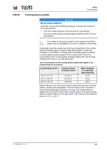
Page 160: ...atment system Choose engine oil with a viscosity suitable for the operating temperature Change the engine oil at the specified intervals Do not mix different engine oils In order to avoid damaging the...

Page 161: ...Tables Technical data BA RC50_RC70 en 00 161...

Page 162: ...hich are described in this operating manual If other fuels are used compliance with the legally specified emission values is not guaranteed The guarantee only applies to diesel fuels which comply with...

Page 163: ...ing system protecting agent by adding a cooling system protecting agent to the cooling water Check the concentration of the cooling system protection agent with commercially available test devices e g...

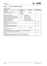
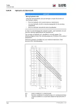
Page 164: ...e specification In order to avoid damaging the hydraulic system each hydraulic oil must have the viscosity appropriate for its intended use The viscosity of hydraulic oil is classified in viscosity gr...

Page 165: ...00 165 U Excessive amounts of heat for example from combustion en gines X Pressure fluid temperature range Vopt Optimal operating viscosity range 1000 Maximum permissible short term viscosity II 100...

Page 166: ...c oil may be used under the following conditions Use only bio hydraulic oil based on special synthetic saturated complex esters The products used and recommended by the manufacturer are listed in the...

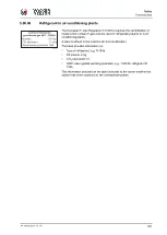
Page 167: ...refrigerating plants or in air conditioning plants A label is affixed to the machine for this identification The label provides information on Type of refrigerant e g R 134a Fill volume in kg CO2 equi...

Page 168: ...etic saturated ester ISO VG Viscosity grade HEES Conditions ISO VG 22 arctic ISO VG 32 winter ISO VG 46 summer ISO VG 68 tropical ISO VG 100 extreme heat Special oil Use only Wacker Neuson special oil...

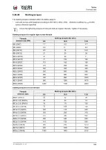
Page 169: ...2 7 4 0 4 7 M5 SW8 5 5 8 1 9 5 M6 SW10 9 5 14 16 5 M8 SW13 21 30 36 M10 SW16 41 60 71 M12 SW18 71 104 122 M14 SW21 113 165 195 M16 SW24 175 255 300 M18 SW27 250 355 420 M20 SW30 350 500 580 M22 SW34...

Page 170: ...ype V3307 CR T Number of cylinders 4 Power ISO 14396 rated speed 55 4 2200 kW rpm Exhaust emissions category EU USA V Tier 4 Carbon dioxide emissions CO2 1 807 2 g kWh Travel drive Working gear speed...

Page 171: ...10 50 l Diesel engine coolant 11 00 l Hydraulic oil 60 00 l Vibrator 5 20 l Air conditioning system R134a 0 85 kg Sound power level Sound power level LWA guaranteed 104 dB A Sound power level LWA repr...

Page 172: ...rbon dioxide emissions CO2 1 807 2 g kWh Travel drive Working gear speed 0 6 0 0 3 7 km h mph Transport speed 0 12 5 0 7 7 km h mph Gradeability with without vibration 55 60 Max permitted longitudinal...

Page 173: ...1 00 l Hydraulic oil 60 00 l Vibrator 5 20 l Air conditioning system R134a 0 85 kg Sound power level Sound power level LWA guaranteed 104 dB A Sound power level LWA representative measurement 102 dB A...

Page 174: ...rt speed 0 12 5 0 7 7 km h mph Gradeability with without vibration 55 60 Max permitted longitudinal incline 20 Max permitted transverse incline 20 Tyres Number of tyres 2 units Tyre diameter min max 1...

Page 175: ...00 l Vibrator 10 00 l Air conditioning system R134a 0 85 kg Sound power level Sound power level LWA guaranteed 104 dB A Sound power level LWA representative measurement 102 dB A Emissions sound pressu...

Page 176: ...rbon dioxide emissions CO2 1 807 2 g kWh Travel drive Working gear speed 0 6 0 0 3 7 km h mph Transport speed 0 12 5 0 7 7 km h mph Gradeability with without vibration 55 60 Max permitted longitudinal...

Page 177: ...1 00 l Hydraulic oil 60 00 l Vibrator 10 00 l Air conditioning system R134a 0 85 kg Sound power level Sound power level LWA guaranteed 104 dB A Sound power level LWA representative measurement 102 dB...

Page 178: ...speed 0 6 0 0 3 7 km h mph Transport speed 0 12 5 0 7 7 km h mph Gradeability with without vibration 55 60 Max permitted longitudinal incline 20 Max permitted transverse incline 20 Tyres Number of ty...

Page 179: ...guaranteed 104 dB A Sound power level LWA representative measurement 102 dB A Emissions sound pressure level at the driver s seat Sound pressure level LpA measured with cab max 79 dB A Sound pressure...

Page 180: ...Tables Dimension sheet 180 BA RC50_RC70 en 00 5 02 Dimension sheet 5 02 01 RC50 5 02 02 RC50p...

Page 181: ...Tables Dimension sheet BA RC50_RC70 en 00 181 5 02 03 RC70 RC70vo 5 02 04 RC70p...

Page 182: ...e machine configuration special attachments slots are correspondingly free or occupied by fuses Please follow the fuse assignment shown on the adhesive label in the engine compartment 5 4 1 2 3 1 Main...

Page 183: ...F11 not used terminal 30 10 A F12 not used terminal 30 10 A F13 Rotating beacon 10 A F14 High beam 15 A F15 Cab heating 10 A F16 Reversing alarm reversing light 10 A F17 not used terminal 15 10 A F18...

Page 184: ...signment Fuse F1 Radio 10 A F2 Tachograph reversing camera 5 A F3 Windscreen washer system spare plug 15 A F4 Air conditioning compressor solenoid coupling air conditioning fan 25 A F5 Blower signal o...

Page 185: ...Alert buzzer Open line short circuit 117 Drive pump Open line short circuit 118 Left turn signal Open line short circuit 119 Left parking light Open line short circuit 122 Parking brake Open line sho...

Page 186: ...in the product Safety Instructions The Special attachments section describes components of the machine that can be operated in addition to the equipment previously described in the manual For the spe...

Page 187: ...caused by crushing or getting caught during assembly Perform installation work on firm ground flat stable horizontal Carry out fitting work only when the engine is stopped Use suitable load suspensio...

Page 188: ...into the cabin roof sunroof or weather protection roof depending on the machine s equipment The FOPS material number is then shown on the ROPS type plate If a design with FOPS safety equipment is dism...

Page 189: ...radiates light over a 360 area A switched on rotating beacon visual identifies marks and safeguards danger areas 6 02 03 Mounting Dismounting WARNING Work above floor level Risk of injury caused by fa...

Page 190: ...g beacon on the contact tube 1 and slide it up to the stop a The electrical connection has been made Tighten clamping screw 4 Dismounting removing rotating beacon 3 1 4 2 2 5 3 Unscrew the clamping sc...

Page 191: ...oader or truck Move the rotating beacon to lock in position 0 for transport Move the rotating beacon to lock in position I for work 6 02 04 Operation 1 2 Switching on rotating beacon Press the rotatin...

Page 192: ...der or a maintenance scaffold To reach the maintenance points on the machine use the steps indicated Do not step on any other machine element or add on part N O T E Dust or sand can impair the functio...

Page 193: ...r damage that arises as the result of misuse or a product malfunction 6 03 03 Operation N O T E Also follow the manufacturer s operating manual during all activities The monitor enables the system to...

Page 194: ...e ground level unless using a stable ladder or a maintenance scaffold To reach the maintenance points on the machine use the steps indicated Do not step on any other machine element or add on part Car...

Page 195: ...the record sheet These include amongst others Driving and stopping times Driving speed Vibration amplitude Vibrator speed 1 3 4 5 2 Driving speed When the machine is moving the tachograph display show...

Page 196: ...eed 2 is used to record the amplitude of the vibrations A thick bar indicate a large amplitude a thin bar a small amplitude On machines with double vibration the recording of the front drum is given p...

Page 197: ...r maintenance work on the dozer blade unless it has been set down Do not step under a raised dozer blade Do not step under suspended loads 6 05 01 Overview 4 1 2 3 1 Dozer blade 2 Wearing edge 3 Hydra...

Page 198: ...enabled Deactivating the floating position Press button 1 or 2 a The floating position is deactivated a The indicator blade 5 then does not follow the irregularities of the ground a The indicator LED...

Page 199: ...Technical data page 160 onwards Basic maintenance work Remove dirt deposits from the dozer blade Check that the screwed connections on the console are tight Replace the wearing edge in good time in or...

Page 200: ...ION Heavy wear edge Injuries caused by crushing or getting caught The wear edge must be replaced by two persons Wear personal protective equipment 1 2 1 2 Prerequisite Wearing edge overhang 1 3 mm Swi...

Page 201: ...de BA RC50_RC70 en 00 201 6 05 05 Dimension sheet Typ Type RC50 RC70 mm 4630 4951 inch 182 3 194 9 mm 1332 1515 inch 52 4 59 6 mm 1118 1339 inch 44 0 52 7 mm 357 308 inch 14 1 12 7 mm 1585 1915 inch 6...

Page 202: ...ries or death caused by crushing or getting caught during assembly Perform installation work on firm ground flat stable horizontal Carry out fitting work only when the engine is stopped Use suitable l...

Page 203: ...surface area widens the field of application of the compactor to cover not only non cohesive and sandy mixed soils but also cohesive and highly cohesive soils 6 06 03 Fitting the padfoot shells N O T...

Page 204: ...g the rear smooth drum scraper 1 2 3 4 Secure the scraper bracket at the rear 1 with a round sling 2 Loosen the screws 3 on one side and remove the fastening elements 4 On the opposite side loosen the...

Page 205: ...er 6 For versions with spacer plates 4 Loosen three screwed connections 3 on each side Remove the spacer plates 4 first Then remove the screwed connections 3 Remove the front crossbeam 1 Set it down o...

Page 206: ...f the shell Tighten the tension strap 2 Mounting the second padfoot shell 2 3 4 1 Start the diesel engine and drive the machine slowly forwards until the shell half 1 lies horizontally Switch off the...

Page 207: ...y under the drum Switch off the diesel engine and remove the ignition key Use a crowbar once more to align the top half shell flush with both ends of the drum Tighten the clamp connection 2 on the fro...

Page 208: ...fastening screws 1 and tighten them Start the diesel engine and drive the machine slowly forwards again until the rear clamp connections 2 are at the front of the drum Switch off the diesel engine an...

Page 209: ...raper holder 5 and remove them together with the scraper holder Move the threaded protective screws 6 to the threaded holes 4 and tighten them Place the scraper 7 for the padfoot drum on the scraper b...

Page 210: ...the padfoot drum scrapers method 2 1 2 3 Padfoot drum clearance 15 mm Loosen the hexagon screw 1 Create the clearance between the drum 3 and the scraper bracket 2 Tighten the hexagon screw 1 Perform...

Page 211: ...hten the hexagon nut 1 of the hose clamp 2 Perform this work on the left and right hand hose clamp mountings 6 06 04 Removing the padfoot shells 2 3 1 1 Padfoot shells 2 Clamp connections 3 Fixing scr...

Page 212: ...5 6 Attach the front crossbeam 1 to the crane with the round sling 2 and tension it slightly Note the position of the centre of gravity For versions with assembly opening on the rear of the crossbeam...

Page 213: ...astening screw 3 on the clamp connection 5 in the middle of the drum Now loosen both mounting screws 4 on the screw head until the nut is flush with the screw shell halves are detensioned Start the di...

Page 214: ...he end of the shell half Start the diesel engine Slowly reverse the machine until the drum is on the clamp connection 3 Switch off the diesel engine and remove the ignition key 150 6 1 Push a square t...

Page 215: ...n the buckle 3 and remove the tension strap 4 Remove the shell half 1 from the drum Fitting the smooth drum scrapers method 1 4 3 1 2 Loosen the clamp connection 1 and replace the padfoot drum scraper...

Page 216: ...th drum off the front crossbeam Screw the scraper holder 6 to the scraper bracket 8 using the fastening screws 7 and tighten Remove the fastening screws 9 from the scraper holder 6 do not remove screw...

Page 217: ...on of scraper bracket Switch off the diesel engine and remove the ignition key Undo the screws 1 Push the scraper bracket 2 towards the drum until the clearance is reached Tighten the screws 1 a The s...

Page 218: ...N O T E The instructions itemized in the Important information about maintenance work must always be followed during all maintenance work Maintenance overview For the first time after 10 operating ho...

Page 219: ...Auxiliary equipment Padfoot shells BA RC50_RC70 en 00 219 Designation Value Unit Weight of rear scraper 70 kg...

Page 220: ......

Page 221: ......
Page 222: ...Wacker Neuson Produktion GmbH Co KG Wackerstra e 6 85084 Reichertshofen Germany www wackerneuson com Tel 49 0 8453 340 32 00 Order no 5100051060 Language en...

Reviews: