User Manual
VWR
®
Collection Model 89508-420
Refrigerated 6.1 cu ft Incubator
Operating and Maintenance Manual 7003734 • Rev. 0
Page 1: ...User Manual VWR Collection Model 89508 420 Refrigerated 6 1 cu ft Incubator Operating and Maintenance Manual 7003734 Rev 0...
Page 2: ...VWR Collection MANUAL NUMBER 7003734 0 10 7 13 Original ccs REV ECR ECN DATE DESCRIPTION By Preface Refrigerated Incubator i...
Page 3: ...adjustments and maintenance must be performed by qualified service personnel s Material in this manual is for information purposes only The contents and the product it describes are subject to change...
Page 4: ...E and the equipment that has been put on the market after 13 August 2005 This product is required to comply with the European Union s Waste Electrical Electronic Equipment WEEE Directive 2002 96 EC It...
Page 5: ...andle Installation 4 4 Operation 5 1 General Functional Checks 5 2 Operation 5 2 Controller 5 2 Accessing Controller Menus 5 3 Changing Chamber Temp Control Setpoint 5 3 Maintenance 6 1 Cleaning 6 1 D...
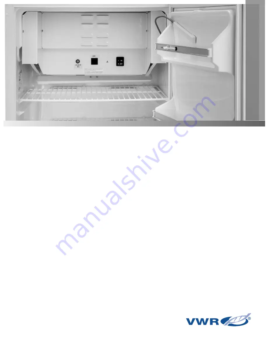
Page 6: ...ude Spacious 6 1 cu ft chamber accommodates up to 114 standard BOD bottles or similar containers Under the counter model with reversible door Two removable adjustable shelves 17 5 x 20 5 50 lbs weight...
Page 7: ...t may be plugged into convenience outlet load current 2A at 115VAC leakage current 250 microamps 3 Disconnect unit power cord from the power supply prior to maintenance and servicing 4 When operating...
Page 8: ...y 114 BOD bottles Shipping Weight 126 lb 57 kg Operating Environment Indoor Use Only Temperature Range 10 C to 40 C Humidity Range 0 to 90 RH Non Condensing Maximum Altitude 6600 ft 2 km Air Clearance...
Page 9: ...the final carrier Usually the firm will send an investigator to ascertain liability Use the list below when unpacking to verify that the complete unit has been received Do not discard packing material...
Page 10: ...quired leveler counterclockwise to increase the height and clockwise to reduce the height The Refrigerated Incubator should be installed on a level stable floor Caution Do not place unit on its top si...
Page 11: ...back walls 4 Place 3 provided adhesive backed mounting anchors at approximately the same spacing on opposite side as existing anchors 5 While supporting door with one hand remove screw securing door...
Page 12: ...While holding the handle in place tighten the screws with a 1 4 nut driver until they are tight against the top inner side of the door DO NOT OVERTIGHTEN SCREWS DO NOT GO INTO THE DOOR Section 4 Unpa...
Page 13: ...located on front panel MENU Used to access menus SET Used to display setting s INCREASE setting t DECREASE setting Display on front panel Displays chamber and set point temperatures in C and prompts f...
Page 14: ...ess SET to display control setpoint display should read 25 0 If the control setpoint or any of the other parameters aren t set correctly use the up or down arrow keys while pressing SET to change the...
Page 15: ...lts arrange samples evenly throughout the chamber Liquid samples should be covered to prevent evaporation and eventual frost build up on evaporator coils particularly when operating below ambient Note...
Page 16: ...ration that determines when the alarm is activated and if the control setpoint can be changed Range 00 to 02 00 Mode Normal mode that allows the user to change setpoint Alarm activates if chamber temp...
Page 17: ...rature reaches the setpoint and is stable protection mode 02 can be set This mode can only be used if the door is to remain shut and other disturbances don t effect the chamber temperature As an added...
Page 18: ...defrosts may be from 30 days to years Defrosting may be necessary when operating at 50 mode as well especially for control temperatures less than 15 0 C Method I For control setpoint down to 10 C thi...
Page 19: ...an accurate temperature measuring device in the geometric center of the chamber 2 Set the controller to the desired operating temperature in 100 cooling mode and allow 2 hours for stabilization 3 Note...
Page 20: ...lows Set DS1 1 A to off up Set DS1 2 B to off up 6 Attach wires previously removed from old controller to new controller 7 Mount new controller and bezel then apply power 8 Refer to Calibration sectio...
Page 21: ...nect incubator from power source 2 Remove shelves from chamber area 3 Remove heater cover at top back of chamber by removing 2 screws on either side 4 Replace the THM1 or HTR1 if necessary then coat e...
Page 22: ...VWR International LLC Radnor Corporate Center Building One Suite 200 100 Matsonford Road Radnor Pennsylvania 19087 United States 610 386 1700 www vwrsp com...