background image

13

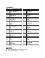
PARTS LIST

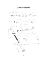
Please refer to schematic drawing on page 14

WARNING

!

l

  Repairs should be made by an authorized repair centre.

l

  Opening this tool could invalidate your warranty.

No.

DESCRIPTION

29

Safety bracket assembly

30

Pin

31

Seal

32

Trigger valve head

33

Spring

34

O-Ring 5.5 x 1.5

35

Trigger valve stem

36

O-Ring 15 x 1.9

37

Trigger valve guide

38

Spring

39

Trigger

40

Locking washer

41

Pin

42

Plate

43

Screw

44

Latch rubber

45

Latch assembly

46

Pin

47

Front plate

48

Bar guide

49

Pin

50

Screw

51

Drive guide

52

Rail A

53

Fixed magazine

54

Stop piece

No.

DESCRIPTION

55

Spring washer

56

Screw

57

Movable magazine

58

Bushing A

59

Lock

60

Screw

61

Screw

62

Locking washer

63

Torsion spring

64

Locking washer

65

Pin

66

Nut

67

Bushing B

68

Screw

69

Pin

70

Feeder shoe

71

Spring

72

Rail B

73

Screw

74

Support

75

Nut

76

Screw

77

Belt hook

78

Soft grip sleeve

79

End cap

80

Air plug

Summary of Contents for 404-7791

Page 1: ...Instruction Manual Manual de instrucciones ITEM NO ART CULO No Combination Brad Nailer Narrow Crown Stapler 404 7791 v070910...

Page 2: ...o material and workmanship for a period of ONE YEAR from date of purchase If defective the product will be repaired or replaced Call the Vulcan Power Tool customer service line at 1 800 482 0131 and a...

Page 3: ...ctrical wires may be encountered try to ascertain whether there is a danger of shock Do not overreach Keep proper footing and balance at all times Do not reach over or across machines which are runnin...

Page 4: ...tions Don t trip over hoses Make sure all connections are tight Disconnect tool from air supply hose before return springs may be improperly mounted When servicing tool use only identical replacement...

Page 5: ...to penetrate Grip tool firmly to maintain control while allowing the tool to recoil away from the work surface as the fastener is driven If the safety is allowed to recontact the work surface before t...

Page 6: ...ng and furniture assembly door and window casing manufacturing aluminum and vinyl siding installation soffit work trim and molding application picture framing and applications where gluing is necessar...

Page 7: ...ose to the tool A as possible within 15 feet is ideal Do not use bottled air or gases Please see figure below l All compressed air contains moisture and other contaminants that can harm the internal c...

Page 8: ...tool from the air supply before loading fasteners 2 Depress the Lock 59 to release the MOVABLE MAGAZINE 57 and pull the magazine out fully as shown 3 Being certain the gun is aimed in a safe direction...

Page 9: ...ol from air supply before loading fasteners doing any disassembly maintenance clearing a jammed fastener leaving the work area moving the tool to another location or handing the tool to another person...

Page 10: ...Oil added through the airline connection will lubricate all internal parts Use only air tool oil Do not use oil with detergents or other additives These can cause damage through accelerated wear to th...

Page 11: ...s too deeply Worn bumper Replace bumper Drive depth is set too deep Turn thumbwheel to the right Air pressure too high Adjust air pressure at regulator Tool runs slowly or has power loss Insufficient...

Page 12: ...on assembly Lack of power Adjust regulator to adequate pressure Slow cycling and loss of power Check cylinder cap spring for broken coils reduced length or if exhaust port is blocked Other Contact tec...

Page 13: ...ve guide 38 Spring 39 Trigger 40 Locking washer 41 Pin 42 Plate 43 Screw 44 Latch rubber 45 Latch assembly 46 Pin 47 Front plate 48 Bar guide 49 Pin 50 Screw 51 Drive guide 52 Rail A 53 Fixed magazine...

Page 14: ...14 SCHEMATIC DRAWING...
Reviews: