background image


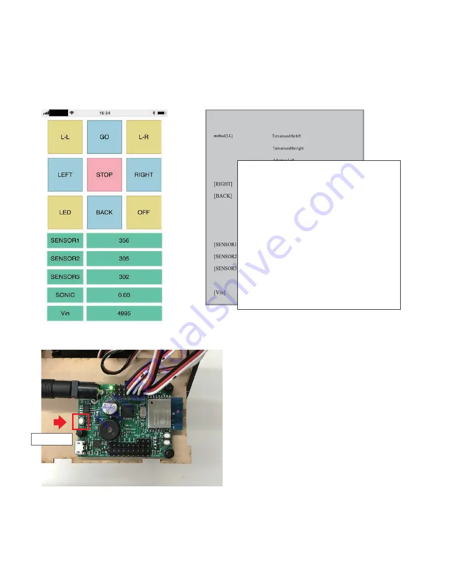
Connect smartphone (or PC) to the Wi-Fi router which the robot is connected to and launch the browser. And then Enter IP address displayed on 

the serial monitor in the URL field and go to the robot controller page. If you connected your device to the Wi-Fi router successfully, you will see 
the page as below. If the page is not displayed, please check and verify whether any miss typing with IP address or power of robot might be not on. 

 Once the HTML is displayed properly, unplug the USB cable from the board and close the head of the robot. After the second time the board will 
get IP address automatically even though disconnected with  the PC. If you cannot open the robot controller page, it is possible that the IP address 
assigned to the board by the Wi-Fi router has been changed. In the case, check the new IP address on serial monitor again. 


If you try to turn off the power of the robot manually, press button for more than 3 seconds and release it. However, power won’t 
be off as long as the robot keeps connecting with a USB cable which please note.


Recession


Stop


SV9,10 of LEDON / OFF


Power-supply voltage


[LR]


[GO]


[LEFT] 


[STOP]


[LED]


[OFF] 

[SONIC]


Operation


Power button


Functions 
[L-L] 

See the left side 

[L-R]  See the right side 
[GO] 

Go forward 

[LEFT]  Turn to the left 
[RIGHT] Turn to the right 
[BACK] Go back 
[STOP] Stop 
[LED]  LED ON/OFF (SV9,10) 
[OFF] Power OFF 
[SENSOR1] Display the value of AN1 
[SENSOR2] Display the value of AN2 
[SENSOR3] Display the value of AN3 
[SONIC] Display the value of ultrasonic sensor 
[Vin]Display the current supply power voltage[mV] 


Summary of Contents for Piccorobo IoT

Page 1: ...Pre assembled version manual Ver 1 0 Piccorobo...

Page 2: ...child when use or assemble this product Besides please pay attention not to let the little child swallow small parts by any occasion This product is not a toy Please make sure to keep an eye on the s...

Page 3: ...ssories M3 screwx10 used for optional accessories woodworking bond used for optional accessories x1 Part of the MDF used for the optional accessories USB cable A to microB x1 robot bodyx1 Please refer...

Page 4: ...detailed instruction of set up VS RC202 Manual https www vstone co jp products vs_rc202 download html After finishing software set up connect the board to your PC via USB port and following instructio...

Page 5: ...DC plug immediately If you neglect such reaction some damage to the servo motor might be caused If the feet touch each other or spacer links hit the edge of the hole the servo horn is determined to be...

Page 6: ...IDE 01 Start Arduino IDE select the Tools Board Generic ESP8266 on menu bar and select other settings as below Depending on your environment it is possible that different information may be displayed...

Page 7: ...al settings by referring to the software set up on VS RC202 Instruction Manual In this section install HTML file which is displayed on smart phone in VS RC202 When you want to install some files excep...

Page 8: ...ument of this function and adjust the deviation The range of the second argument is 500 500 Example setServoOffset 1 100 Set offset 100 to SV1 left foot setServoOffset 2 100 Set offset 100 to SV2 righ...

Page 9: ...error message espcomm_upload_mem failed is displayed it may be that port selection is wrong or USB cable is not connected to the PC Set the baud rate of the serial monitor to 115200 When the SSID and...

Page 10: ...e robot controller page it is possible that the IP address assigned to the board by the Wi Fi router has been changed In the case check the new IP address on serial monitor again If you try to turn of...

Page 11: ...ss are correct but the robot controller page is not displayed on browser You might have forgotten to upload the HMTL file to the board Upload the HTML file in accordance with instruction on P18 of the...

Reviews: