background image

29 30

33

35

34

3132

22 23

24 25

28

2627

VOL

16 18

17

15

14

20

19

21

13

12

11

10

9

1

2 3 4 5 6

7

8

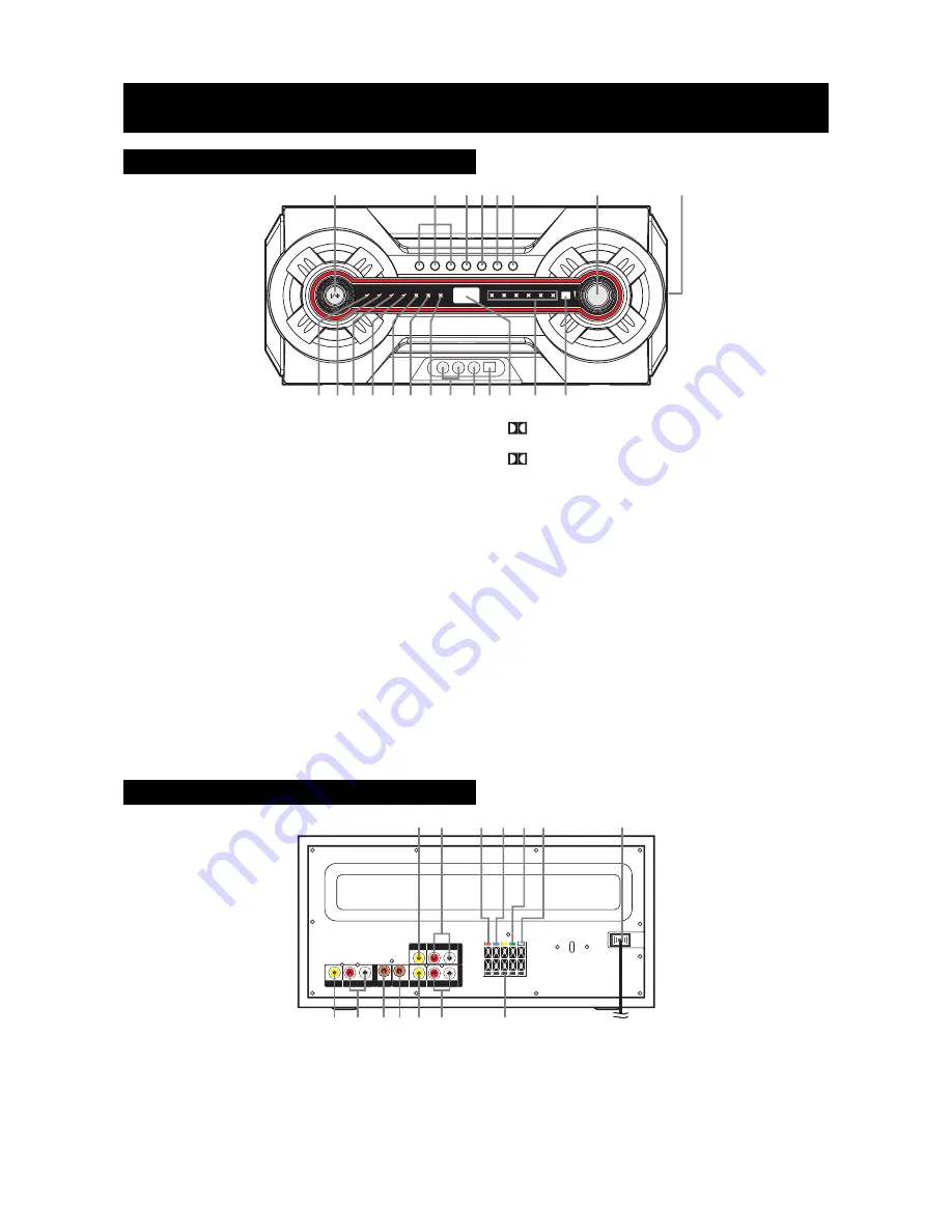
Rear Panel

FUNCTION CONTROL

1. STANDBY/ON button

Turns the unit ON, or puts the unit into STANDBY mode.

2. AV1/2/3 buttons

Press AV1 or AV2 to enter “auto-detected/auto-switching”
mode, press again to switch to “forced analog” mode.
Press AV3 button to select the AV3 input.

3. PL button

Change the output channels or the output sound mode.

4. BASS button

Adjust the bass level.

5. SURROUND DELAY button

Adjust the surround delay time.

6. CENTER DELAY button

Adjust the center delay time.

7. /- button

Adjust the volume or the level of corresponding function.

8. BUILT-IN SUBWOOFER
9. STANDBY/DELAY indicator

Lights when the unit is in standby mode or setting
the surround/center delay.

10.3 STEREO indicator

Lights when 3 STEREO is active.

Front Panel

22.  TV VIDEO OUT jack
23.  TV AUDIO OUT (R & L) jacks
24.  Right Front Speaker terminals
25.  Right Rear Speaker terminals
26.  Left Rear Speaker terminals
27.  Left Front Speaker terminals
28.  Power Cord

E - 3

11.

 PRO LOGIC indicator

Lights when Dolby Pro Logic is active .

12.

 DIGITAL indicator

Lights when Dolby Digital is active.

13.AV1 indicator

Lights when the unit is in AV1 mode.

14.AV2 indicator

Lights when the unit is in AV2 mode.

15.AV3 indicator

Lights when the unit is in AV3 mode.

16.AV3 AUDIO IN (L&R) jacks

Connect to AUDIO outputs on external audio source.

17.AV3 VIDEO IN jack

Connect to VIDEO outputs on external audio source.

18.DIGITAL IN

Connect to DIGITAL (OPTICAL) outputs on external audio
source.

19.Display window

Display the level of corresponding function.

20.Speaker indicators

Lights when the corresponding speaker is active.

21.Remote Control sensor

Accepts the remote control signals.

29.  AV1 VIDEO IN Jack
30.  AV1 AUDIO IN (R & L) Jacks
31.  AV1 DIGITAL AUDIO IN (VCR/SAT)Jack
32.  AV2 DIGITAL AUDIO IN (DVD) Jack
33.  AV2 VIDEO IN Jack
34.  AV2 AUDIO IN (R & L) Jacks
35.  Center Speaker terminals

Summary of Contents for XG3000

Page 1: ...XTREME GAMING SURROUND SOUND SYSTEM Instruction Manual Please read the instruction manual carefully before using your unit VCR AV INPUT AV INPUT AV INPUT 3 DVD I N P U T VOL...

Page 2: ...und Speakers 5 Positioning the Speakers Subwoofer 6 Setting the Input Mode and Listening Channels 6 Video Audio Input Output Setting 7 8 SOUND ADJUSTMENT 9 Adjusting the Balance 9 Setting the Bass Lev...

Page 3: ...o 2 hours before turning the power on or gradually heat the room up and dry the unit before use Notes on Maintenance Do not use volatile chemicals on this unit Clean by lightly wiping with a soft clot...

Page 4: ...ified service personnel Servicing is required when the apparatus has been damaged in any way such as power supply cord or plug is damaged liquid has been exposed to rain or moisture does not operate n...

Page 5: ...3 TV AUDIO OUT R L jacks 24 Right Front Speaker terminals 25 Right Rear Speaker terminals 26 Left Rear Speaker terminals 27 Left Front Speaker terminals 28 Power Cord E 3 11 PRO LOGIC indicator Lights...

Page 6: ...on Adjust the surround delay time 3 5 1 2 9 10 8 7 6 4 Using the Remote Control Correctly Attention Take out the PVC sheet before operating the remote control 1 Point the remote control at the remote...

Page 7: ...ends of each speaker wire into the corresponding jacks on the rear of the Unit matching the color tube on the end of the speaker wire to the color coded connector Caution To prevent damage to the uni...

Page 8: ...e unit will be in Auto Detect mode and the light labelled AV1 you press the AV1 or AV2 button once the unit will be in Auto Detect mode and the light labelled AV1digital and will automatically switch...

Page 9: ...deo cable included Refer to your TV s owner s manual To record the playing signal connect AUDIO OUT to the recordable equipment Recordable cassette player Recordable MD player etc Watching a DVD 1 Con...

Page 10: ...speaker channel You can enjoy the dynamic realistic sound of Dolby Pro Logic Surround by connecting the unit to the equipment which gives Dolby Pro Logic signal with a coaxial cable or audio cable Th...

Page 11: ...o adjust the delay time of the center speaker The digit in the display window will change to show the setting value The center delay ranges from 0 to 5 Note If you do not press any button within few s...

Page 12: ...ital or analogy sound Check the speaker connections of the inoperative channel Check the speaker cord connection and speaker location Check the speaker connection for proper phasing Check that the spe...

Reviews: