background image

Federal Communication Commission Interference Statement 

 
This equipment has been tested and found to comply with the limits for a Class B digital device, pursuant to Part 

15 of the FCC Rules. These limits are designed to provide reasonable protection against harmful interference in 

a residential installation. 

This equipment generates, uses and can radiate radio frequency energy and, if not installed and used in 

accordance with the instructions, may cause harmful interference to radio communications. However, there is no 

guarantee that interference will not occur in a particular installation. If this equipment does cause harmful 

interference to radio or television reception, which can be determined by turning the equipment off and on, the 

user is encouraged to try to correct the interference by one of the following measures: 

Reorient or relocate the receiving antenna. 

Increase the separation between the equipment and receiver. 

Connect the equipment into an outlet on a circuit different from that to which the receiver is connected. 

Consult the dealer or an experienced radio/TV technician for help. 


FCC Caution

 :To assure continued compliance, any changes or modifications not expressly approved by the party 

responsible for compliance could void the user's authority to operate this equipment. (Example - use only shielded interface 

cables when connecting to computer or peripheral devices). 


FCC Radiation Exposure Statement 


This device complies with Part 15 of the FCC Rules. Operation is subject to the following two conditions: 

(1) This device may not cause harmful interference, and (2) This device must accept any interference received, 

including interference that may cause undesired operation.


To satisfy FCC RF exposure compliance requirements, this device should be used in hand-held, hand-operated 

configurations only. The device and its antenna must maintain a separation distance of 20cm or more from a 

person’s body, except for the hand and wrists, to satisfy RF exposure compliance. 

This device is designed to be used in a person’s hands and its operating configurations do not support normal 

transmissions while it is carried in pockets or holsters next tot a person’s body. 


Summary of Contents for SRT-9000

Page 1: ...MODEL SRT 9000 REMOTE ENGINE STARTER WITH ALARM SYSTEM OWNER S MANUAL 1...

Page 2: ...PLAY 12 C CHIRP INDICATOR 12 D PARKING LIGHT 12 E ACTIVE ARMING ARM LOCK 13 Ajar Warning Silent Arming Sensor By Pass Hidden Alarm Mode F PASSIVE ARMING 13 Passive Arming with Passive Door Locking Pas...

Page 3: ...re of 1 Keep the transmitter out of children s reach 2 Do not leave anyone in the vehicle while running on remote control 3 Alert servicing personnel that the vehicle can be started automatically 4 Do...

Page 4: ...ture Car jacking Battery Level Engine Running Melody Mode Count Down Timer Parking Timer Vibration Mode Alert Alarm Timer Start switch switch button Level and push switch switch Button Button 2 Button...

Page 5: ...an charge the battery indoors While the battery of the Remote Transceiver is under charging Push the button the screen will display Battery charging Charge Input USB Input C MAIN PAGE 1 Press the butt...

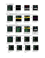
Page 6: ...onds press the button 1 2 3 or 4 to remote control button configuration you selected Note If 5 seconds of inactivity expired or push the button the transceiver button configuration mode will exit Spin...

Page 7: ...d it will display previously setting Press the button 2 to change the setting Press the button and the setting is done E P1 2 BUTTON LOCK SETTING Example Set the Button Lock Enable Spin down the switc...

Page 8: ...eter 30 min Note When parking meter trigger presses any button to stop the beeper Spin down the switch to the page 2 Press the button 2 Press the button 1 three times to set the parking timer to 30 mi...

Page 9: ...button 1 and the hour digit flashes Press the button 2 to set the hours digit to 08 for adjusting Press the button 1 and the minute digit flashes for adjusting Press the button 2 to set the minute dig...

Page 10: ...for adjusting Press the button 2 to set the hour digit to 02 Press the button 1 and the minute digit flashes for adjusting Press the button 2 to set the minute digit to 30 Press the button 3 to start...

Page 11: ...1 NAME OF CHANNEL SETTING Example Set Name of channel 4 to GARAGE DOOR Spin down the switch to the page 5 Press the button 1 and the flashes for setting Spin up the switch to set the G Press the butt...

Page 12: ...ock Disarm System Press twice within 3 seconds 3 Button 3 2 second Trunk Release Channel 3 Press and Hold for 2 seconds Passive Arming By pass While the system Disarmed 4 Turn Off The Remote Start But...

Page 13: ...ional time to confirm the sensor bypass mode was activated The sensor bypass feature is programmed to activate for one arming cycle only The security system will return to normal operation during the...

Page 14: ...H PASSWORD PIN CODE Unlike valet switch easily found and defeated this security system allows the consumer to program a password pin code Offering a higher level of security 1 Enter the vehicle and tu...

Page 15: ...screen 2 During panic mode the normal function of this transmitter button will be suspended The transmitter and buttons can be used to lock and unlock the door if the option is installed however once...

Page 16: ...During this 15 seconds period of chirping you will be alerting to push the valet switch once to turn off the car jacking feature If not it will enter second timer car jacking c 65 seconds after the sy...

Page 17: ...buttons at the same time to active Auxiliary 3 function Activate The AUXILIARY 4 Spin up the switch to the page 3 and then press the Auxiliary 4 button or press the transmitter and buttons at the same...

Page 18: ...hicle while engine running on the remote start 1 Insert the ignition key and turn it to ON not the start position 2 Press the brake pedal Note If the brake pedal is pressed before the key is in the ON...

Page 19: ...page 5 and then select the Daily start 3 The parking lights will flash and the siren will chirp 6 times indicating the daily timed start mode is activated Cancel the timer start Timer start will be ca...

Page 20: ...e 1 Activate the warn away first stage of the shock sensor system will emit a short chirp 2 Activate the full alarm second stage of the shock sensor system will emit a long chirp 3 Continue to test th...

Page 21: ...nt from that to which the receiver is connected Consult the dealer or an experienced radio TV technician for help FCC Caution To assure continued compliance any changes or modifications not expressly...

Reviews: