background image

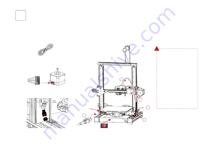
Wire connection

5

1. Connect the yellow-labeled cables with "Z1" and "Z2" on 6 pin(4 wires) ports to Z-axis motors; 

将6针(4线)端口上带有黄色标签丝印“Z1”,“Z2”

的线分别与左右两个Z轴电机连接;


2. Connect the port of black cable to Z-axis limit sensor; 

黑色线端口与Z轴限位传感器端口对插;

3. Insert the XE-axis assembly zcable; 

插上XE轴组件转接排线;

4. Insert the extruder cable into the extruder; 

插上喷头排线;

5. Plug in the power cord (as shown) and toggle the switch to turn on the power.    

Z-axis motor port

Z-axis limit sensor

Power cable *1

Z-axis limit sensor

Z-axis motor

Z-axis motor

10

5

2

1

4

3

设备接线

Z轴电机接口

Z轴限位传感器接口

电源线*1

插上电源线(如示意图)拨动开关打开电源。

Attention

· Damage might occur if voltage is 

set incorrectly. Make sure the 

current input voltage matches to 

your local mains 

(115/230 V).

· Plug in power cord and turn 

power switch to 1 to turn it on.

· Do not disconnect the cables 

when the printer is powered on.

注意

·  如果电压设置不正确,可能会造成

损坏。选择正确的输入电压以匹配您

的本地电源

(115/230V)

·  连接电源线并将电源开关拔至I档即

可开机。

·  当机器通电时,请勿断开连接线。

Z轴限位传感器

Z轴电机

Z轴电机

Summary of Contents for Aquila Pro

Page 1: ...20210926 3D Printer User Manual Note Each printer is tested before leaving factory It is normal if there are some residues in extruder or some tiny scratches on the build plate It won t a ect the prin...

Page 2: ......

Page 3: ...products For your convenience please read the manual carefully before using it Operate the printer accordingly Voxelab team is always at your service contact us at any time if you need any assistance...

Page 4: ...ter on a shaking place It may a ect the printing quality Children and untrained personnel are not allowed to operate the printer alone Operate the printer in a well ventilated environment Some materia...

Page 5: ...nd spool holder X axis right xed block X X axis tensioner X Platform clip Power switch and socket Screen Tool box Printer base Voltage regulator Y axis limit sensor Y Y axis motor Y E axis motor E Fil...

Page 6: ...sh German USB connection printing WIFI Online printing U Wi Input 3mf stl obj fpp bmp png jpg jpeg Output G File GX File Gcode File Equipment Parameters Model Print volume Forming technology Extruder...

Page 7: ...umatic joints 2 Diagonal Pliers 1 Power cable 1 Wrenches and screwdrivers M4 T nuts 2 Nozzle 1 Filament 1 Hexagon socket head spring washer combination screws M5x45 5 Hexagon socket button head screws...

Page 8: ...ly up at least 15 cm to the position as shown then use four M5x45 screws to x gantry frame with the base Hexagon socket head spring washer combination screws M5x45 4 M5x45 06 Installation video can be...

Page 9: ...1 Hexagon socket button head screws M5x8 2 Pass the display cable through the cable xed buckle rstly then connect it to the screen Finally install the screen onto printer base side with two M5x8 screw...

Page 10: ...ack as shown place the spool holder on the rack and x on the pro le with screws as shown M4 T nuts 2 Hexagon socket button head screws M4x6 2 M4x6 M4 T nut Connect the lament tube Back Install it on t...

Page 11: ...X axis limit sensor and synchronous belt is in a proper elasticity Front A B A B 09 X X Tips Manually rotate the X axis and Y axis tensioners to the appropriate tightness Reference standard Press the...

Page 12: ...5 Plug in the power cord as shown and toggle the switch to turn on the power Z axis motor port Z axis limit sensor Power cable 1 Z axis limit sensor Z axis motor Z axis motor 10 5 2 1 4 3 Z Z 1 Atten...

Page 13: ...ing process please do not touch the lament tube and nozzle cable 11 Leveling operation video can be found on Voxelab Youtube channel Check the steadiness of the build plate before leveling If the buil...

Page 14: ...and the printing platform to about 0 1 mm Thickness of a piece of A4 paper 2 We can use a piece of A4 paper to assist in leveling so that the nozzle only scratches on the A4 paper Adjust the four leve...

Page 15: ...3 Note The UI information is only for reference the actual UI may be di erent Tap Level Z Calibration the leveling sensor starts to test the build plate one by one When it nished the Z axis calibratio...

Page 16: ...f you need to adjust temperature for some reasons please tap Settings Temperature PLA ABS preheat setting to adjust parameter 14 Note The UI information is only for reference the actual UI may be di e...

Page 17: ...e to let lament pass through 3 Insert lament into lament tube tap Load to feed lament to the nozzle Loading is completed when lament is extruded at the nozzle Filament can be fed to the nozzle manuall...

Page 18: ...sembly repeat the load process 2 To replace lament during the printing process tap Settings select lament replacement icon it will pause the print and unload the lament After unloading completed pleas...

Page 19: ...h drive 1 Ensure that the build plate has been leveled before printing 2 Ensure that the lament has been loaded in an appropriate approach 3 Please clean extruder before printing Load the lament for a...

Page 20: ...Print 18 Note The UI information is only for reference the actual UI may be di erent UI...

Page 21: ...e The UI information is only for reference the actual UI may be di erent Tap Settings Wi Fi open the Wi Fi function choose the Internet and save the password Wi Fi connection Wi Fi Wi Fi WIFI Wi Fi Wi...

Page 22: ...and check the IP address 2 Open VoxelMaker click Print Connect Machine input the Printer IP address and click Connect There is a connect icon when it connected successfully Connect printer by Wi Fi 19...

Page 23: ...he upgrade completed please delete the rmware le in the U disk to avoid upgrading repeatedly next time Get the rmware les Enter the o cial website www voxelab3dp com and download them at Download Cent...

Page 24: ...22 Note The UI information is only for reference the actual UI may be di erent UI...

Page 25: ...cooling fan port Hotbed wire port Nozzle wire port Platform temperature detection port Z axis limit sensor port Screen port Reserved port Fuse Power port Y axis motor and limit sensor port Z axis mot...

Page 26: ...se re level it If printing e ect is not accurate enough check the tension of synchronous belt and make it neither too loose nor too tight When synchronous belt working well check the steps per mm unde...

Page 27: ...electric motor 2 Contact us by email listed Email support voxelab3dp com Q What if the les are garbled and cannot be read A Repair the model before slicing Q What if the build plate cannot be heated A...

Page 28: ...any abrasion 2 Check whether the extruder is clogged use a needle to clean it if necessary 3 Con rm whether the lament feeding wheel is stuck if it is please clean it up Q What if o set occurs on the...

Page 29: ...gether with the printer or download this form from www voxelab3dp com ll in this form and mail it to support voxelab3dp com After sales service shall not be provided without this form Please contact y...

Page 30: ...not be con rmed Damage s caused by improperly or incorrectly performed modi cations alterations or repair Damage s caused by operation under improper environment damp wet or other extreme weather Exte...

Page 31: ...1 Voxelab 3D 12 FFF 3D 3 2 Voxelab 3 4 Voxelab Voxelab U TF USB Voxelab Voxelab 3D Voxelab SAC20200804...

Page 32: ...District Jinhua Zhejiang China Physical objects and nal images might be distinct from the user manual due to di erences between printer models Voxelab reserves nal explanation rights Voxelab Voxelab v...

Reviews: