Assembly instructionsVOSS OBW 501
SG sensor
Strain gauge sensor for on-board weighing systems
Axle weight measuring – at its most precise way
Page 1: ...Assembly instructions VOSSOBW501SGsensor Strain gauge sensor for on board weighing systems Axle weight measuring at its most precise way...
Page 2: ...installation The sensor has to be stored dry and free from humidity Do not remove the sensor from the ESD protection bag before installing it in the vehicle Do not use the sensor data to control safet...
Page 3: ...tructions 1 Grinding and cleaning of surfaces To protect the sensor it hast to be covered by a protection cover and by sealing The cable has always to be protected by a corrugated tube Avoid bending t...
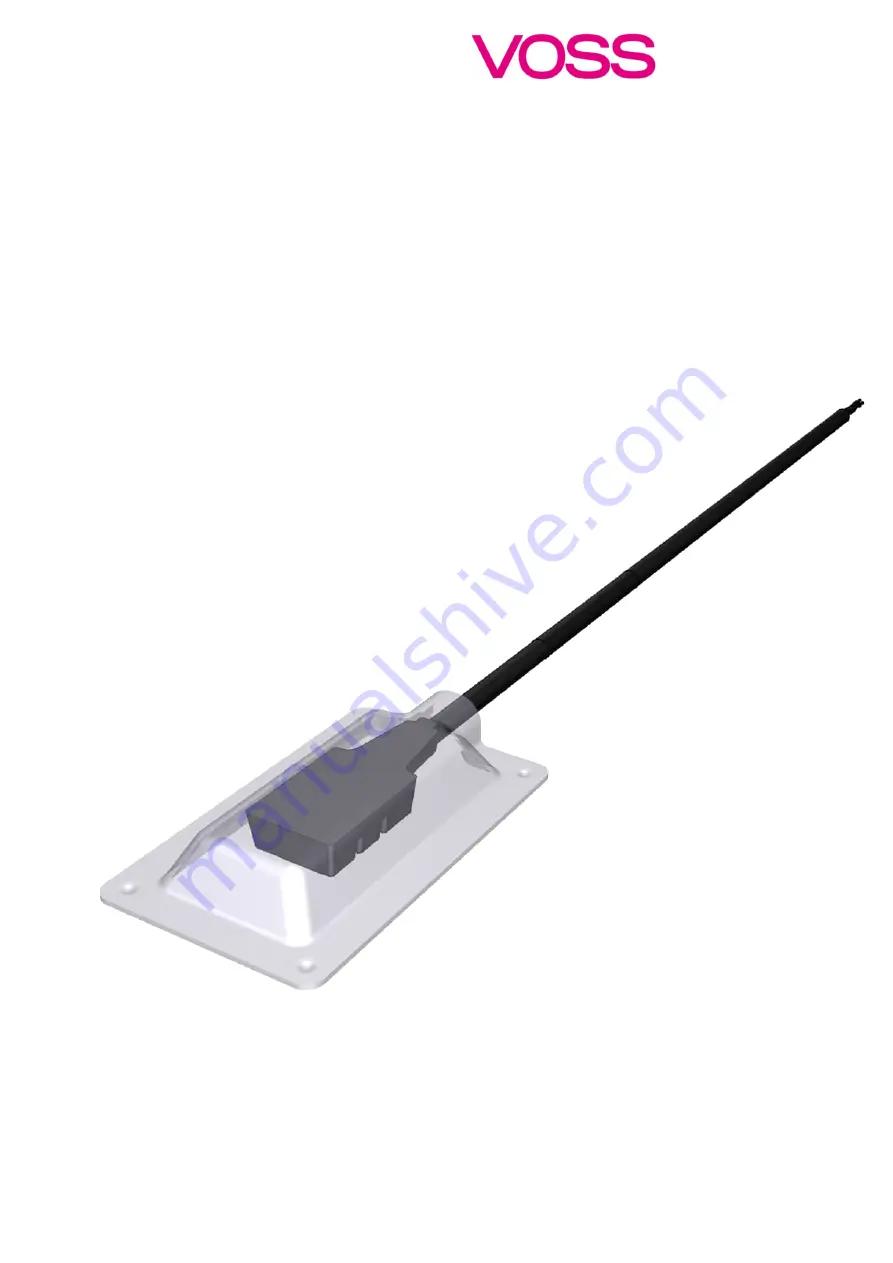
Page 4: ...W501SGsensor Fig 1 VOSSOBW501 SG sensor with cable Fig 2 VOSSOBW 501 SG sensor with metal protection cover and corrugated tube 2 Electrical connection possibilities Fig 3 Connector Tyco HDSCS Pin1 VBA...
Page 5: ...Assembly instructions VOSSOBW501SG sensor Page 5 of 22 3 Complete sensor set Fig 5 VOSSOBW 501 SG sensor with Tyco HDSCS and metal protection cover complete sensor set...
Page 6: ...drilling machine with 60 and 120 grain abrasive paper 120 abrasive paper 240 cleaning cloths lint free cloths and cleaning solvent acetone 2 propanol mixing ratio 1 1 Use the middle of the axle as as...
Page 7: ...Continuously polish the surface by using drilling machine with grain 120 Fig 8 Polishing the surface using drilling machine with grain 120 Step 4 Grind the surface fine by hand by using abrasive paper...
Page 8: ...e performed on an area at least as large as the sensing part ca 30 mm x 20 mm Fig 10 Fine grinding of the surface by hand by using abrasive paper with grain 240 Step 6 Final result of the grinding pro...
Page 9: ...d cleaning solvent for the final cleaning During this process you need to change the cloth until the cloth remains white after wiping This may take several attempts Prepared surface has to be complete...
Page 10: ...ns white after wiping This may take several attempts Prepared surface has to be completely free of dirt paint dust oil and grease Fig 16 Finally white lint free cloth after cleaning process Step 10 Fi...
Page 11: ...2 Wipe clean all grinded surfaces of the protection cover with a white lint free cloth and cleaning solvent Fig 19 Cleaning of protection cover Step 13 Carefully wipe all the surface of the sensor wit...
Page 12: ...ompound CARSYSTEM UNIFLEX PU with single part cartridge press is recommended or comparable products spray paint with corrosion protection varies depending on individual vehicle and cable ties Use new...
Page 13: ...with mixer tip and two part adhesive applicator Use only one mixer tip for one sensor assembly For two sensors only if adhesive is added to both sensors in less than one minute Remember to order extra...
Page 14: ...ive applicator Step 4 3 Prepare the adhesive start dispensing the adhesive upwards until the air bubbles in mixer tip have gone Fig 27 Preparing the adhesive dispending adhesive Step 4 4 Prepare the a...
Page 15: ...tip When adhesive bonding temperature of the axle should be above 10 C 50 F Fig 29 Applying the adhesive Step 6 Immediately after applying the adhesive attach the sensor to the prepared surface and ap...
Page 16: ...ion Vehicle can be moved without any problems We recommend vehicle to be unloaded after HI calibration until next day Table 1 Time after sensor s are adhesive bonded with Panacol GTH T Step 8 Prepare...
Page 17: ...uding shoulders with the adhesive and sealing compound Avoid air bubbles if possible Hold the nozzle inside the adhesive and sealing compound during filling Nozzle can be shortened with knife to make...
Page 18: ...sh it completely to the surface Make sure that no adhesive and sealing compound reaches the corrugated tube to ensure that water could drain later in operation Fig 37 Smoothing out the sealant Step 14...
Page 19: ...ct the VOSSOBW 501 SG sensor to the Kimax SCU by using the following cable connection Fig 40 VBAT Red GND Brown Signal White or with the corresponding counter part of the Tyco HDSCS connector Pin1 VBA...
Page 20: ...e the analog output voltage has already saturated at 4 5 V although the maximum total weight of the vehicle has not yet been reached the gain must be reduced Caution If the gain is changed in this ste...
Page 21: ...nsor do a 2 point LO and HI calibration for the weight calculation curve in the used ECU of the vehicle Please refer to the user manual of the used on board weighing ECU Fig 43 2 point calibration dia...
Page 22: ...rademarks Drawings of the VOSSOBW501 SG sensor may not be reproduced or made accessible to third parties without our prior consent Technical modifications and errors excepted Contact VOSS Automotive G...