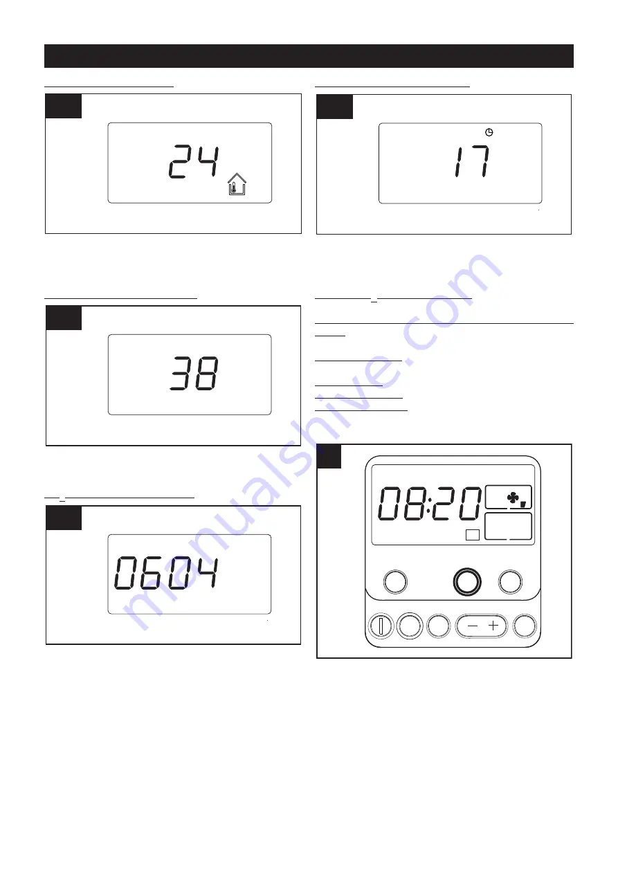
indoor temperature (fig.24b)
during normal operation, detected by the temperature
sensor located in the intake duct, coming from the
rooms served, before the heat exchanger;
Current humidity display (fig.24c)
(detected by the sensor located in the house outlet duct,
before the heat exchanger);
CO2 percentage display (fig.24d)
(detected by the CO2 sensor placed in the home air inlet
shaft, before the heat exchanger).
Residual operating time at Vmax ,(fig.24e)
depending on preset Timer duration (see TIMER button)
Other information displayed automatically, depending
on the conditions:
Excess CO2 threshold warning (see “Warning/error
signals")
Value set during initial configuration of Min and Max
Speed (values from 00 to 69, 10 to 99: only during the
installer set up stage)
Clockface symbol: if the Timer function is set (see
“TIMER button”)
Clogged filters (see “Warning/error signals”)
Battery charge low (see “Warning/error signals”)
System malfunction (see “Warning/error signals”
TIMER button
(fig.25)
It forces the device to operate at Max Speed for 10 min
(press key for 0.5 sec), 20 min (press twice), 30 min
(press three times), or continuosly (press four times).
Pressing the key for a fifth time (OFF) restores operation
at the previously set speed, unless over-ridden by the
sensors.
25
25
DISPLAY
TIMER
MODE
SET NEXT ENTER
Su
AUTO
24e
24e
CO2(ppm)
24d
24d
RH(%)
24c
24c
24b
24b
°C
33
ENGLISH


