
58
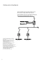
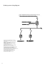
Shilded wire must be provided only from power panel side and not from fan
side.
In case on signal line you are going to install junction boxes to connect single
fan signal line to main line, between junction boxes and signal connector from
inverter you must use same wire RS485 used for signal line.
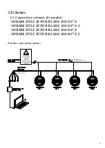
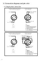
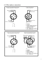
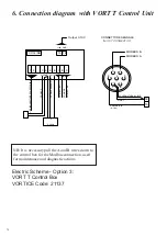
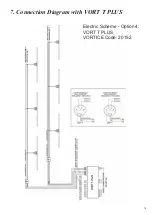
For connection and wire colour, you have to follow electric diagram.
Warnings for maintenance and diagnostic actions
Many maintenance interventions and diagnostic actions of the fan can be
done by remote connection.
In order to do this, it is, however, necessary to identify exactly the fan and
connect to it.
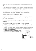
Therefore, DURING THE INSTALLATION IT IS MANDATORY:
Pull always the A and B wires down to the switchboard (to connect with
1)
the fan)
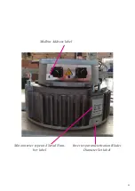
Set down in a scheme the Serial Number and the Modbus Address of each
2)
motor, as well as their placement (to univocally identify each single ma-
chine) in case of maintenance
Verify that in the same line there are not in-
3)
stalled two motors with identical Modbus Ad-
dresses.
Controller
Summary of Contents for Nordik HVSL Super Blade 110 V Series
Page 1: ...NORDIK HVLS SUPER BLADE E SUPER BLADE 110 V Instruction booklet COD 5 571 084 939 23 07 2021 ...
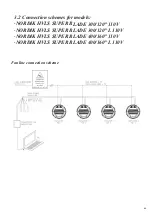
Page 25: ...25 INVERTER MOTOR ELECTRONICS QUICK CONNECTORS ...
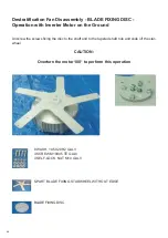
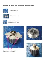
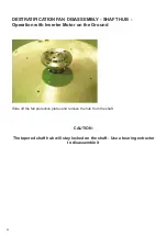
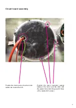
Page 28: ...28 Destratification Fan assembly ...
Page 56: ...56 Attachment 2 Electric connection ...
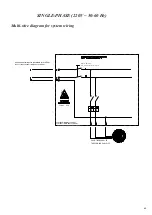
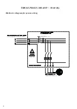
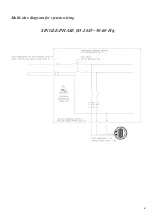
Page 67: ...67 Multi wire diagram for system wiring SINGLE PHASE 85 264V 50 60 Hz ...
Page 78: ......
Page 79: ......


