


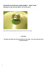
40
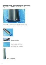
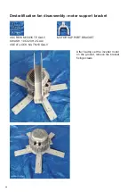
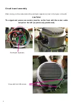
Support bracket and rod assembly
ROD GALV
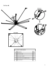
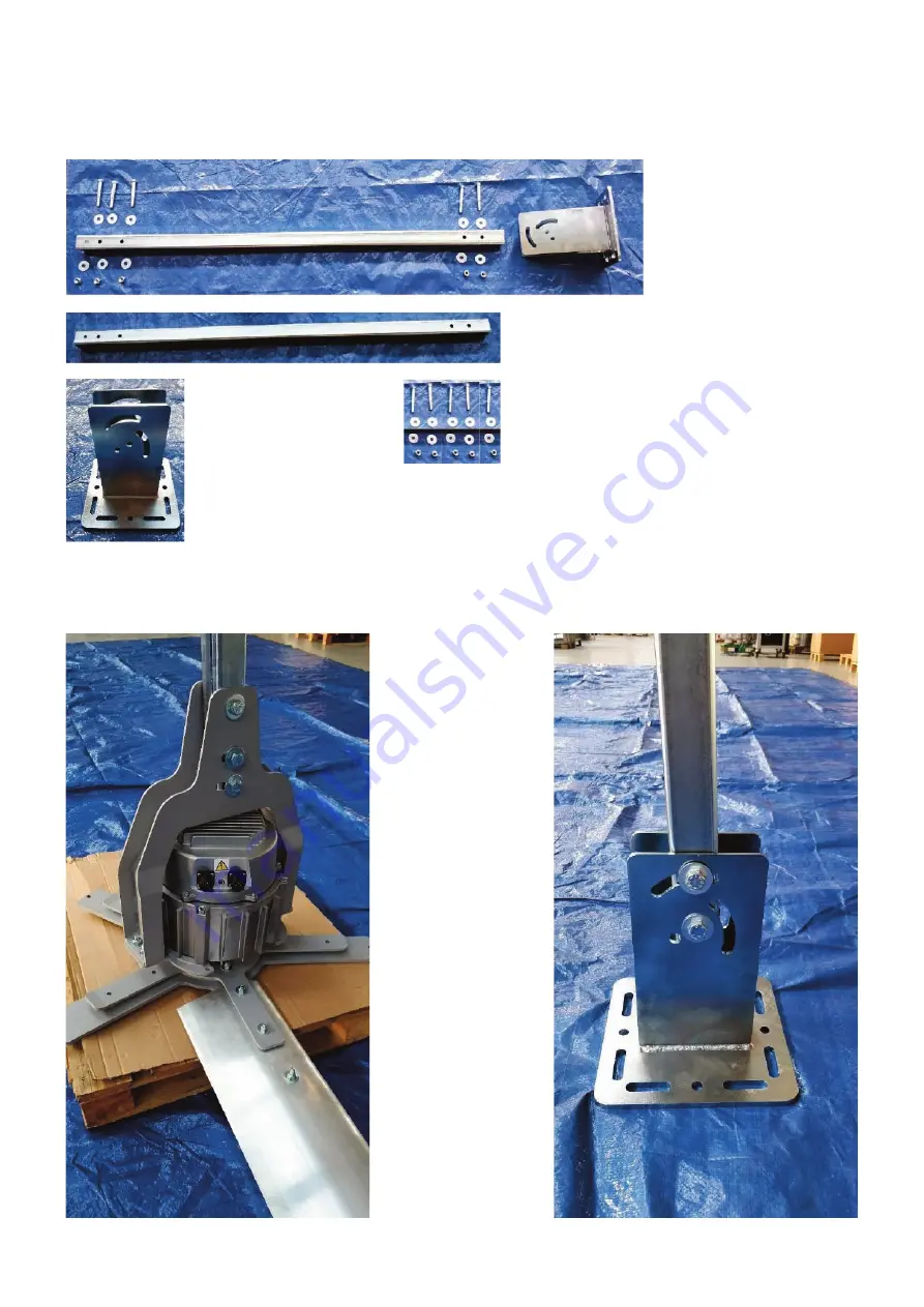
Insert the rod in the motor support bracket on the side where the three holes are present. The
opposite side of the rod, with the two holes, must be inserted in the rod support bracket, as shown
in the figures on the right. Fix with screw, washers and nut shown on the left.
ROD SUPPORT
BRACKET
5 SCREW M12X90 TETF GALV
10 WASHER M12X36 H2.5 GALV
5 SELF-LOCK. NUT M12 GALV
Summary of Contents for Nordik HVSL Super Blade 110 V Series
Page 1: ...NORDIK HVLS SUPER BLADE E SUPER BLADE 110 V Instruction booklet COD 5 571 084 939 23 07 2021 ...
Page 25: ...25 INVERTER MOTOR ELECTRONICS QUICK CONNECTORS ...
Page 28: ...28 Destratification Fan assembly ...
Page 56: ...56 Attachment 2 Electric connection ...
Page 67: ...67 Multi wire diagram for system wiring SINGLE PHASE 85 264V 50 60 Hz ...
Page 78: ......
Page 79: ......


