voran EBP580 Translation Of Operating Manual Download Page 48

Single belt press EBP580


Version: 166000000, M0017267B_EN208-240-60D  
Date: 28.11.2017


                    - 48 / 52 -


First clean any installed Washing Machine or serially connected mill and then clean the press as 
follows: 


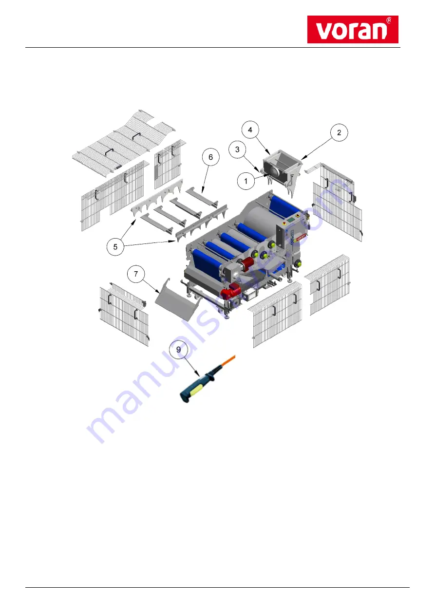
Picture 10.5.1-1) Cleaning the Belt press 


1.)  Remove protective grating.  


2.)  Unscrew the cable from dosing switch (Fig. Pos. 1). 


3.)  Pull out safety end-switch (Fig. Pos. 2).  


4.)  Open the locking hooks (Fig. Pos. 3) and remove dosing tank (Fig. Pos. 4).  


5.)  Remove mash conveyor (Fig. Pos. 5), scrapers (Fig. Pos. 6) and end scrapers (Fig. Pos. 7).  


6.)  Start cleaning mode.  


Summary of Contents for EBP580

Page 1: ...Single belt press EBP580 Version 166000000 M0017267B_EN208 240 60D Date 28 11 2017 1 52 Translation Operating manual part 1 Single belt press EBP580 3 x 208 240V 60Hz...

Page 2: ...RE STARTING OF THE MACHINE LINE 19 4 1 GENERAL 19 4 2 MOUNTING BELT LUG 19 4 3 CONTROLS AND SETTINGS WORK BEFORE FIRST STARTING UP RE STARTING OF LINE 20 4 3 1 Setting the pressure regulator 21 4 3 2...

Page 3: ...G 44 10 3 SERVICING INTERVALS 45 10 4 LUBRICANTS OVERVIEW 46 10 5 SERVICING AND REPAIRS MACHINE LINE COMPONENTS 47 10 5 1 Cleaning 47 10 5 2 Reading off operating hours 49 10 5 3 Setting the pressure...

Page 4: ...ARNING OF DANGEROUS LIVE ELECTRICAL POWER SUPPLY Before any servicing or checking work is undertaken all parts or supply lines on the machine that are marked with this sign must be switched free from...

Page 5: ...at the machine line is only operated under perfect technical operational conditions and giving full account to the proper use WARNING AGAINST GENERAL DANGERS Ensure that all possible faulty functions...

Page 6: ...ion 0 with a padlock and or disconnect the main plug 1 4 Organizational measures NOTE Before starting up the machine line the operating personnel must without fail be familiar with the Operating Manua...

Page 7: ...nd released in writing by the machine line suppliers This also applies to the installation and setting of the safety devices and safety equipment This also includes the welded constructions of the bea...

Page 8: ...locked before the start of the work It must be assured that the machine line is not switched on again by appropriate measures or the posting of a second person When carrying out work in an unsecured...

Page 9: ...and secured against being started up again In the event of malfunctions the line machine must be shut down immediately and locked Ensure that immediate and professional trouble shooting of the malfun...

Page 10: ...es on the machine line marking sources of risk e g Picture 1 6 1 Caution live voltage HINWEIS The safety devices must not be left aside nor made in effectual Where this is not assured no liability can...

Page 11: ...be possible to remove them with the use of tools The possibility of loosening them manually is not permitted Protective devices may only be removed for the period of maintenance and servicing The mac...

Page 12: ...fety covers Regulation clothing operator training Standing beneath hanging loads The endangering of the ground personnel is possible from falling loads Wear safety helmets observe safety notes for ser...

Page 13: ...may only be operated when in a technically perfect condition in a professional manner and when the operator is fully aware of the safety and danger aspects Recognized weaknesses or faults that may red...

Page 14: ...11 2017 14 52 1 10 Training record Line machine Trainer Date of training Place of training Training content Participant confirmation Name of participant Signature of participant you confirm with your...

Page 15: ...eared motor Voltage 230 400V 50HZ IP56 Capacity 0 75 kW Rotary speed 1400 Transmission i 151 Pneumatic system The press is provided with a manometric switch that switches the press off when the workin...

Page 16: ...checked for any transportation damage this is to be recorded in the delivery certificate and reported to the Customer Service Department Ensure that the machine is not damaged by knocking it or settin...

Page 17: ...ricity supply Three phase current 208 240 V 3 phases earthing Fuse protection 16 A neutral Water supply for belt cleaning a For high pressure cleaners supplied by Voran K rcher type HD 7 18 C Water su...

Page 18: ...sewer you have to talk with your regional sewer contractor Connect the washing machine to the safety switch Fig Pos 3 Compressed air supply The compressor must have a maximum pressure of 10 bar and a...

Page 19: ...NING AGAINST GENERAL DANGERS The operator must ensure just to handle materials which aren t capable also especially during the milling process to create ignitable substances fluids aerosol steam explo...

Page 20: ...GAINST GENERAL DANGERS Before cleaning the device or checking the connection cable to see if this has been twisted or damaged switch the machine off without fail and pull out the mains connector plug...

Page 21: ...g work and check that the belt runs correctly centred on the rollers Information on the setting of the screen belt can be found in the chapter Servicing and Repairs under 10 5 4 Setting of the screen...

Page 22: ...t is then pulled in between the screen belt and the first large roller and in a first pressing is pre pressed by approx 70 After this first pressing the pressing product goes on via a guide roller to...

Page 23: ...on 1 Switch on compressor 2 Open the hand valve on the maintenance unit Fig Pos 1 by turning it The tensing cradle Fig Pos 2 then moves forwards and tightens the screen belt The compressor must be set...

Page 24: ...he Belt press is supplied with power by switching on the main switch Fig Pos 1 Switch the key switch Fig Pos 2 to automatic Unlock the emergency stop button 2 Press the button Fig Pos 4 3 Choose a lan...

Page 25: ...to the main menu 6 After switching on the screen belt fig 9 the cleaning fig 10 and the brush cleaning fig 11 can be switched on as well by pressing the corresponding button 7 By pressing again the bu...

Page 26: ...28 11 2017 26 52 6 2 3 Setting belt speed The belt speed can be adjusted continuously 1 Press display fig 1 2 The screen belt operates slower or faster 35 90 Hz by pressing the arrows Fig Pos 2 3 Pre...

Page 27: ...e cleaning time must be maintained at least 4 min 1 belt circulation 3 The cleaning is activated by pressing the button Start Fig Pos 4 4 For continuous cleaning the waiting time must be set to 0 6 2...

Page 28: ...mash amount in the dosing tank to prevent an overflowing of the mash The application width is adjusted by the adjusting plates Fig Pos 4 as required The application amount can be adjusted variably by...

Page 29: ...L1 L2 P1 P2 P3 P4 P5 G N D 1F U 1 I I I 1 3 5 2 4 6 13 21 14 22 G V 2M E 06 1 0 1 6A 1 5 L S IS S V 008iC 5 1F D IP S chalter position auf P N P V C D 01 H auptschalter M ain sw itch B rstenreinigung...

Page 30: ...g n e tve n til W a te r m a g n e tic va lve 0 1 2 kW 0 4 2 A B a n d re in ig u n g B e lt cle a n in g P ro je ktn a m e E in b a n d p re sse E B P 5 8 0 S in g le b e lt p re ss E B P 5 8 0 S e...

Page 31: ...4 V 7 2 W 3 A 3 A 1 ID E C F T 1 A C 1 2 R A B P ro je ktn a m e E in b a n d p re sse E B P 5 8 0 S in g le b e lt p re ss E B P 5 8 0 S e ite n b e sch re ib u n g S te u e rstro m kre is C o n tro...

Page 32: ...a is P N O T S 3 S a fe ty re la y P N O Z S 3 n d e ru n g D a tu m N a m e D a tu m 1 2 0 4 2 0 1 7 G e z G e p r N o rm E N 6 0 2 0 4 1 1 6 6 0 9 8 0 0 0 v o rh e rig e S e ite n ch ste S e ite B l...

Page 33: ...e ite B la tt le tz te s B la tt 5 6 4 8 Z e ich n u n g s N r X 2 1 3 OUT 5 X1 2 X2 6 A1 1 A2 3 Y2 Y1 4 8 OUT 5 X1 2 X2 6 A1 1 A2 3 Y2 7 Y1 4 8 OUT 5 X1 2 X2 6 A1 1 P E 3 D 9 P E 6 D 0 X 2 6 X X 2 4...

Page 34: ...e rig e S e ite n ch ste S e ite B la tt le tzte s B la tt 6 7 5 8 Z e ich n u n g s N r in tern e xtern 3 A 1 3 A 1 3 A 1 3 A 1 D ig ita l In p u t In itia tor E n d a b stre ifer P ro xim ity sw it...

Page 35: ...te n sion I4 3 A 1 D ig ita l In p u t Z u stim m ta ster R e in ig u n g sm odus P e rm issio n S w itch C le a n in g m odus I5 3 A 1 D ig ita l In p u t I6 3 A 1 D ig ita l In p u t S t rung B rste...

Page 36: ...6 0 2 0 4 1 1 6 6 0 9 8 0 0 0 v o rh e rig e S e ite n ch ste S e ite B la tt le tz te s B la tt 8 9 7 8 Z e ich n u n g s N r 2 4 V D C 7 A 9 2 4 V D C 9 A 0 0 V G N D 7 A 9 0 V G N D 9 A 0 P E 7 D...

Page 37: ...40V 60Hz 110205304ULCSA 2M1 Drive Experts GmbH 1 A9F07204 iC60H 2P 4A C 10KA LS switch 160300042 3F1 Telemecanique Groupe Schneider 1 Power supply unit 24V 72W 3A 121100301 3T1 Weidm ller GmbH 1 Touch...

Page 38: ...Single belt press EBP580 Version 166000000 M0017267B_EN208 240 60D Date 28 11 2017 38 52 8 Pneumatic 8 1 Pneumatic diagram EBP580 Picture 8 1 1 Pneumatic...

Page 39: ...ety principles must be followed without fail INFORMATION When faults tables on the separate machine line parts are not otherwise given you can find further information on the precise settings in the c...

Page 40: ...en several fault press Fcs Up Fig Pos 2 or Fcs Dwn Fig Pos 3 By pressing REVERSE the particular error can be selected After opening and closing the safety fence the safety relay and frequency converte...

Page 41: ...oid subsequent damage and downtime BEFORE OPENING UNPLUG Interrupting your work on the machine power supply and secure against accidental before reconnecting it and turning Non compliance can mean sev...

Page 42: ...e operator to the person responsible NOTE The line machine must in general be regularly cleaned and tidied Checks must be carried out at regular intervals in order to assure an operation of the machin...

Page 43: ...s are to be added to this Operating Manual and presented to the manufacturer on request Spare parts It is essential that spare parts should be stored on site to assure a high machine line availability...

Page 44: ...eet building no Zip code city country Product name Date ____________________________ Time from ____________ to____________ Fault dealt with Used spare parts Further supply Yes no ID number Name Clearl...

Page 45: ...g and Repairs Servicing intervals pneumatics EBP 580 Work to be carried out A B C Check piston rod for visible damage X Check cylinders connections and pipelines for leaks X Check bellows cylinder for...

Page 46: ...C Check dosing lever for functionality X Check weld seams for visible damage tears X Check the functionality of the membrane switch X Servicing intervals attachment and scraper complete Work to be car...

Page 47: ...ersonal injury 10 5 1 Cleaning NOTE Use for the daily cleaning process commercial cleaning and caring qualified for food and disinfectant PROTECTIVE GLOVES and WEAR EYE PROTECTION Always wear protecti...

Page 48: ...d then clean the press as follows Picture 10 5 1 1 Cleaning the Belt press 1 Remove protective grating 2 Unscrew the cable from dosing switch Fig Pos 1 3 Pull out safety end switch Fig Pos 2 4 Open th...

Page 49: ...Pos 1 operating hours can be read 10 5 3 Setting the pressure regulator After servicing and repair work has been carried out above all when parts have been replaced pressure regulators must be correct...

Page 50: ...in the opposite direction of the band alignment tighten the screws and the machine on for a trial run Repeat the process described in Section 2 to the main web is running again in the middle 10 5 6 T...

Page 51: ...quipment For mounting a new screen belt proceed as follows 1 Remove discharge plates and tubs 2 Remove scrapers and mash conveyor 3 Pull out defective belt 4 Place the screen belt in front of the mach...

Page 52: ...Single belt press EBP580 Version 166000000 M0017267B_EN208 240 60D Date 28 11 2017 52 52...

Reviews: