background image

8

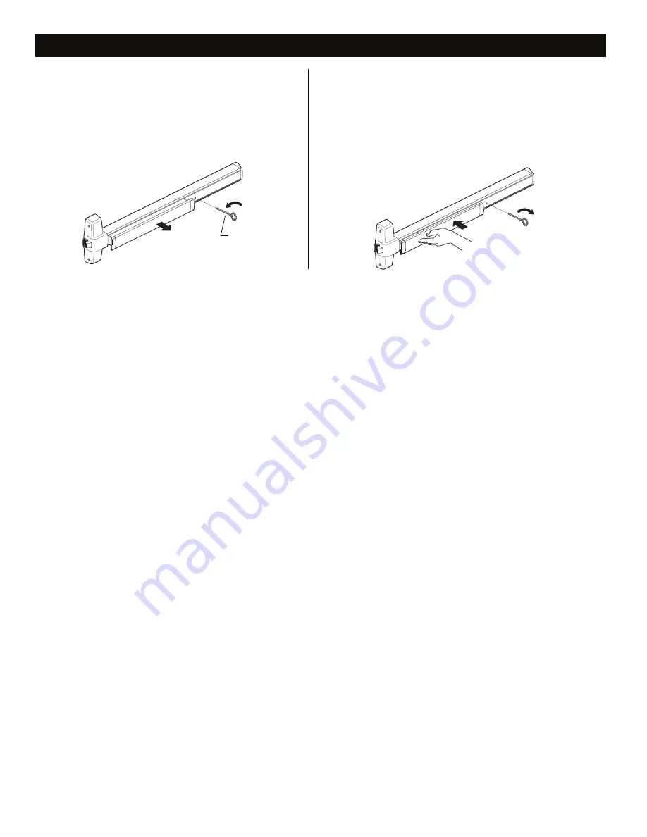
HEX DOGGING INFORMATION

Note: Panic devices are shipped dogged

(pushbar down).

1. To undog device, place hex key in hole as

shown and turn counterclockwise releasing

pushbar.

To undog exit device:

Note: Dogging is recommended during times of

high traffic through door.

1. Depress pushbar.

2. Place hex key in hole as shown and turn

clockwise. Pushbar stays in down position.

To dog exit device:

Hex key

CCW

CW

Summary of Contents for CDXP98

Page 1: ...Screw chart 2 Preparation chart 3 Device installation 4 6 Retrofit installation 7 Hex dogging information 8 CD cylinder dogging 9 Cut device 10 954 strike installation 10 Special tools needed Taps 10 24 1 4 20 Drill bits 7 25 1 8 1 4 5 16 3 8 13 32 Please give these instructions to building owner after device is installed Rim Exit Device XP98 XP99 Installation Instructions ...

Page 2: ...ew G 8 18X3 8 Threadcutting 4qty Metalframe 1 4 20X3 4 3 qty F D 10 16X3 8 Threadcutting 2 qty Endcapscrew E 10 24X1 4 qty 10 24X1 1 2 4 qty 10 X 1 1 4 Wood screw 4 qty Surface mountor Sexbolts 2 1 4 door Surfacemount wood Sexbolts 1 3 4 door C 10 24X1 3 8 4 qty 10 24 X 1 7 8 4 qty 990Trims 1 3 4 door 990Trims 2 1 4 door Packaged with trim SCREW CHART B Metalframe 1 4 20X3 4 6 qty Woodframe 14X1 1...

Page 3: ... Sex bolts 25 Drill 10 24 tap 1 8 Drill pilot 1 deep 1 4 Drill device side 13 32 Drill trim side 13 32 Drill thru Metal Wood Metal Wood End cap bracket 2 holes Prepare holes after center case is mounted and device is leveled PREPARATION CHART RHRshown LHR opposite Go to Device Installation on next page before using this preparation chart C L C L X X Outside cylinder applications Mark with template...

Page 4: ...page 10 Strike Body against door A See Screw Chart on page 2 for screw type and size C L 7 Drill 1 4 20 tap 2 places Metal DEVICE INSTALLATION Strike Body against door Note For retrofit applications where an existing 98 99 Rim device is being replaced see Retrofit Installation on page 7 Position template against strike and on and mark door 909 strike shown 954 strike also works with this template ...

Page 5: ... sizes D E C IMPORTANT Two support screws MUST be installed With NL drive screw removed key locks and unlocks lever knob or thumb piece For trims listed below REMOVE NL drive screw 996L 696TP 990TP 996K 697TP With NL drive screw installed key retracts latch bolt DO NOT remove NL drive screw for the following applications NL EO DT trims and 98 99 2 double cylinder devices i e TP 2 L 2 and K 2 If tr...

Page 6: ...perational check until device functions as described above Strike plate 7 Drill 1 4 20 tap Metal Locate hole at center of slot 7 Drill 1 4 20 tap 2 places 909 Strike 954 Strike A B 9 Verify gap between latch bolt and strike and adjust strike as needed Strike MUST have some gap Gap no more than 3 16 12 Note about the XP latch operation The XP latch bolt operates differently from a standard latch bo...

Page 7: ...ion strike against door C Mark and prepare 2 outer holes for 1 4 20 and install screws Existing center strike hole Locking plate 1 3 Mark and prepare 2 new support holes in door A Align plastic template with existing holes as shown B Mark 2 new holes as shown C Prepare2newholesperchartbelow 25 Drill 10 24 tap Metal Wood 1 8 Drill pilot 1 deep 2 new holes Plastic template Go to page 5 6 and continu...

Page 8: ...ace hex key in hole as shown and turn counterclockwise releasing pushbar To undog exit device Note Dogging is recommended during times of high traffic through door 1 Depress pushbar 2 Place hex key in hole as shown and turn clockwise Pushbar stays in down position To dog exit device Hex key CCW CW ...

Page 9: ... mechanism case Std mortise cylinder Mortise cylinder cam Std mortise cylinder Mortise cylinder cam CD function conversion Figure 1 Figure 2 Std mortise cylinder Cylinder collar Dogging plate cover Offset toward pushbar Cylinder locating washer Cylinder lock nut Mechanism case 2 Turn cylinder key clockwise approx 1 8 turn for standard dogging Dogging procedure 1 Depress pushbar DO NOT USE ON FIRE ...

Page 10: ...a being cut CUT DEVICE Cut device square and remove all burrs 1 1 2 minimum clearance with endcap removed Devicealigned with mounting holes 3 Cut device square NOTE Device must be cut square for proper end cap fit 4 Slide anti rattle clip into device Tape Cover plate flush to end of channel Pushbar Remove anti rattle clip 1 Measure amount to cut off device Anti rattle clip 2 Minimum If 5 8 diamete...

Page 11: ...11 ...

Page 12: ... Allegion 2016 Printed in U S A 911000 00 Rev 05 16 e Customer Service 1 877 671 7011 www allegion com us ...

Reviews: