FAX version 911373_00(1) Page 5 of 9
5
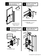
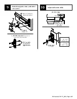
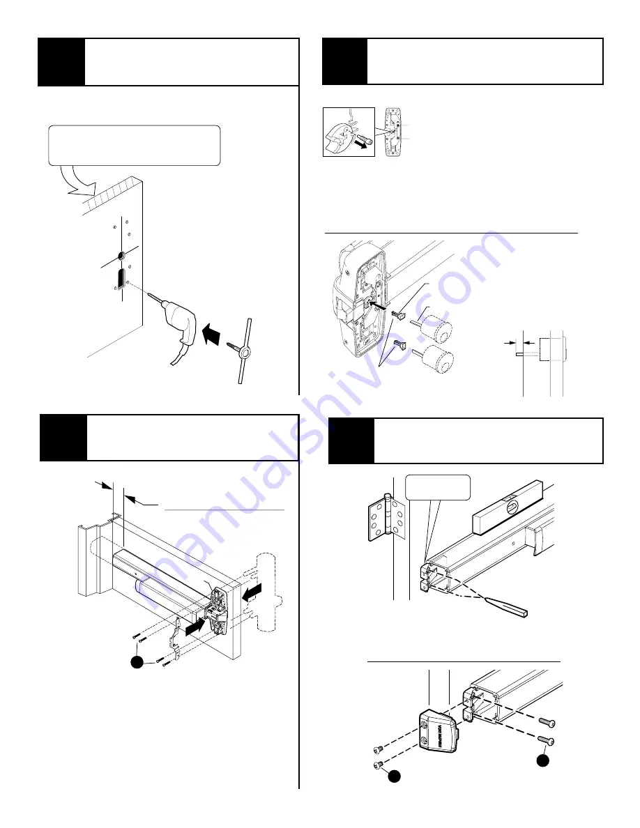
Prepare lock side of door
for device and trim.
See
Preparation Chart
on page 3 for
drill, tap, and cut-out information
X
X
See trim instructions for pull side door
preparation. Line
X
-
X
in trim instructions
is same as vertical device
C
.
L
9
7
Install trim (if using) and secure
device center case to door.
center
case
Trim
(optional)
1-1/2 Minimum clearance
(with end cap removed)
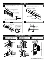
if device is too long for
door, see
Cut Device
on page 9
B
8
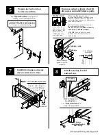
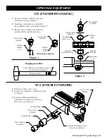
Install mounting bracket
and end cap.
Secure
mounting bracket
and end cap
Mounting
bracket flush
Level
device
Mark and prepare 2
mounting holes
See
Preparation Chart
on
page 3 for preparation
C
D
5
Cut tailpiece
if needed
1/2
D
oor
surface
6
Tailpiece
Tailpiece guide
Rotate tailpiece
guide to match
tailpiece
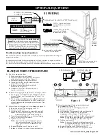
If using an outside cylinder, check NL
drive screw and install tailpiece guide.
When installing trim that has a
functional lever, knob, or thumb piece
AND an outside cylinder to lock and
unlock the trim, remove NL drive screw
from back of device.
DO NOT remove NL drive screw for
the following application:
NL, EO, DT, TP-2, L-2, and K-2 trims or
with 98/99-2 (double cylinder).
With
BE
trim, device may need
rehanded. Look for instructions on
back of trim.
Note: When the NL
drive screw is left in
back of device, the
outside cylinder
will function only
as a Night Latch.
NL drive screw


