Vollrath Stoelting F231 Service Manual Download Page 46

Service Manual #513659 

38 

Model F231

B. DRIVE MOTOR REMOVAL

1. 

Disconnect machine from electrical supply before 
removing any panels for servicing.

2. 

Remove the back panel and the side panel.

3. 

Remove the electrical cover plate from the back 
of the motor.

4. 

Identify (mark) wires and remove them from the 
motor.

5. 

Loosen the belt tension adjustment bolt and 
remove the belt. (Refer to Figure 6-3)

7. 

Remove the motor mounting bolts.

8. 

Loosen the two allen head screws from the pulley.

9. 

Remove the pulley and key from the motor shaft.

C. DRIVE MOTOR INSTALLATION

1. 

Place the drive motor in position and install the 
four mounting bolts.

2. 

Place the pulley and key on the motor shaft.

NOTE

Do not tighten the pulley screws until after the belt 
tension has been properly adjusted.

3. 

Install the belt and tighten the tension adjustment 
bolt.

4. 

Use a Burroughs Belt Tension Gauge to set the 
tension for the drive belt. Set the belt tension to 
40-45 lbs.

5. 

Using a straightedge, align the drive motor pulley 
with the gearbox pulley. Tighten the two allen 
head screws.

6. 

Install wiring according to wiring diagram (located 
behind the left side panel). Install electrical cover 
plate on the motor.

7. 

Install back and side panels.

6.3 DRIVE 

MOTOR

The F231 has two drive motors. They are used to rotate 
the auger assemblies. An internal, normally closed, cen-
trifugal switch starts the drive motor. The motors have an 
internal thermal overload.

A. DRIVE MOTOR TEST

1. 

Turn the machine off by pressing the Main Power 
Off/On button and disconnect the machine from 
the electrical supply.

2. 

Remove the back panel and a side panel.

3. 

Loosen the belt tension adjustment nut and remove 
the belt.

4. 

Connect power to the machine.

5. 

Turn the machine on by pressing the Main Power 
Off/On button.

6. 

Press the right arrow, SET, then the SEL button 
to access the technician level on the control.

7. 

Activate the drive motor through the Left Output 
Control or Right Output Control menus which are 
located under Utilities in the Testing and Manual 
Operation screen. Refer to Section 4 for details.

8. 

Go to the Test Monitoring screen under Utilities. 
The motor current should not be above 3.5 on 
single phase machines or 3.8 on three phase 
machines.

NOTE

The motor amps are based on 230VAC supply 
voltage.

9. 

After the test, stop the motor by exiting the Testing 
and Manual Operation section. Turn the machine 
off and disconnect from the electrical supply.

10. 

Install the belt and tighten the tension bolt.

11. 

Use a Burroughs Belt Tension Gauge to set the 
tension for the drive belt. Set the belt tension to 
40-45 lbs.

12. 

Using a straightedge, align the drive motor pulley 
with the gearbox pulley. Tighten the two allen 
head screws.

WARNING

Hazardous voltage

Make sure the machine is off when disassembling 
for servicing. The machine must be disconnected 
from electrical supply before removing any access 
panel. Failure to disconnect power before servicing 
could result in death or serious injury.

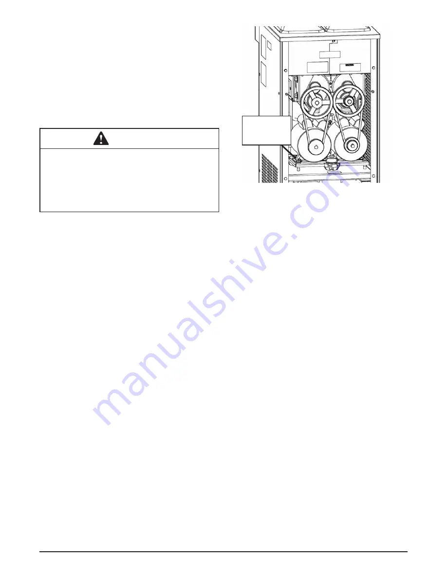
Figure 6-3 Belt Tension Adjustment

Tension

Adjustment 

Nut

Summary of Contents for Stoelting F231

Page 1: ...Model F231 SERVICE MANUAL Manual No 513659 Rev 2...

Page 2: ......

Page 3: ...built prior to date of change DO NOT ATTEMPT to operate the machine until instructions and safety precautions in this manual are read completely and are thoroughly understood If problems develop or q...

Page 4: ...ecific safety information the following safety defini tions are provided to assist the reader The purpose of safety symbols is to attract your at tention to possible dangers The safety symbols and the...

Page 5: ...21 Added support for I O update Changed High Torque Error 2 detection to be directly from motor amperage and not from a calculated factor VERSION 20 27 Released on 12 28 10 Added Unit Serial Number to...

Page 6: ...ge VERSION 17 19 CONTINUED Storage CutOut changed to 32 F was 31 F Storage Offset changed to 4 F was 2 F Storage Off Time changed to 13 min was 2 min Storage On Time changed to 130 sec was 200 sec Sto...

Page 7: ...mbled Parts 11 3 5 Sanitizing Machine Parts 11 3 6 Cleaning the Machine 11 3 7 Assembling the Machine 12 3 8 Sanitizing 12 3 9 Freeze Down and Operation 13 3 10 Fine Consistency Adjustment 13 3 11 Mix...

Page 8: ...4 5 7 Solenoid 34 5 8 Filter Drier 36 5 9 Capillary Tube 36 6 Electrical and Mechanical Control Systems 6 1 IntelliTec2 Control 37 6 2 Contactors 37 6 3 Drive Motor 38 6 4 Capacitors 39 6 5 Gearbox 39...

Page 9: ...provides a uniform product The F231 is designed to operate with almost any type of commercial soft serve or non dairy mixes available including ice milk ice cream yogurt and frozen dietary desserts Th...

Page 10: ...3 Phase 208 240 VAC 60Hz running amps 12A 10A connection type NEMA 6 20P power cord provided NEMA L15 20P power cord provided International Option 1 Phase 220 240 VAC 50Hz Compressor 12 000 Btu hr R 4...

Page 11: ...33 F Sleep 2 CutOut 30 5 F Default Off Time 300 sec Storage Storage Refrigeration Active Storage CutIn 37 5 F Storage CutOut 32 F Storage Offset 4 F Storage Off Time 13 min Storage On Time 130 sec Sto...

Page 12: ...ensor failure will keep the control in Serve and Standby modes only 4 A freeze cycle will reset the stir cycle 5 Serve Mode is active for the Temperature Consistency setting and monitors CutIn Tempera...

Page 13: ...ng All labels must remain legible for the life of the machine Labels should be checked periodi cally to be sure they can be recognized as warning labels If danger warning or caution labels are needed...

Page 14: ...ttings option and press the SEL button Then move the cursor to the User Preferences and press the SEL button C On the User Preferences screen move the cursor totheContactInformationUSBUpdateandpress t...

Page 15: ...quired 1 Press the SEL button to enter the Modify Time and Date screen 2 Move the cursor to the setting that needs to be changed and press the SET button 3 Use the arrow buttons to change the setting...

Page 16: ...Service Manual 513659 8 Model F231...

Page 17: ...curs 3 2 OPERATING CONTROLS AND INDICATORS Before operating the machine it is required that the op erator know the function of each operating control Refer to Figure 3 1 for the location of the operat...

Page 18: ...ort machine statistics 3 3 DISASSEMBLY OF MACHINE PARTS Before using the machine for the first time complete machine disassembly cleaning and sanitizing proce dures need to be followed Routine cleanin...

Page 19: ...nsult your local and state health codes for the procedures required in your location A Prepare Stera Sheen or equivalent cleaner in 2 gallons of 90 to 110 F 32 to 43 C water following manufacturers in...

Page 20: ...auger into the freezing cylinder and rotate slowly until the auger engages the drive shaft H Applyathinlayerofsanitarylubricanttotheinside and outside of the auger support bushing Install the bushing...

Page 21: ...ot to dispense product H The machine dispenses product at a reasonable draw rate If the machine is overdrawn the result is a soft product or a product that will not dispense at all If this occurs allo...

Page 22: ...oper product serving temperature varies from one manufacturer s mix to another Mixes should provide a satisfactory product in the 20 F to 24 F range Diet and low carb mixes typically freeze to proper...

Page 23: ...d sequence Press the left ar row button from the Current Status screen to access the passcode input screen The specific readings and parameters available depend on the keypad sequence entered The lowe...

Page 24: ...row to go to the second screen Cylinder The performance information displayed is for the selected cylinder To change cylinders press the SEL button Consistency This is the current consistency number o...

Page 25: ...d Sleep 2 Mode Stir Off is the amount of time between stir cycles Stir cycles occur in Serve Mode Standby Mode and Sleep 2 Mode D Advanced Settings 2 of 2 TheAdvanced Settings menu contains standby an...

Page 26: ...will be displayed G User Preferences The User Preferences menu contains language options temperature units service contact information and touch pad lockup The screen is available to the Manager and...

Page 27: ...d unlock the keypad for self service locations D Export Machine Stats The Export Machine Stats screen allows you to export all the data and statistics stored in the control Connect a USB flash drive t...

Page 28: ...ed to Open G Motor Calibration The Motor Calibration screen is used when a motor is replaced or the control firmware is updated Move the cursor to the correct option and press the SEL button to calibr...

Page 29: ...time in sleep mode The screen shows a running total the total for the previous day and the total for the previous week for both statistics Restore Factory Settings This will reset all machine setting...

Page 30: ...revi ous week C Machine Statistics 3 of 10 The Machine Statistics screen 3 of 10 provides the time and date that the freezing cylinder was last cleaned This value is recorded when the Clean button is...

Page 31: ...hat had the error Up to 25 errors are stored Press the up or down arrow to scroll through the errors Select the Status at Time of Error option to view data for the time the error occurred The Help opt...

Page 32: ...l has completed this step it will automatically restart O Enter the technician password to the control by pressingtherightarrow SET thentheSELbutton P Navigate to the Utilities menu and select the Nex...

Page 33: ...irty place a wet towel over the condenser C Using compressed air or CO2 tank blow out the dirt from the back of the condenser Most of the dirt will cling to the wet towel D Analternativemethodistoclea...

Page 34: ...Service Manual 513659 26 Model F231...

Page 35: ...or qualified service personnel only Anybody work ing with refrigerants must be certified as a Techni cian TYPE I as required by 40 CFR 82 Subpart F and hold all State and or local refrigerant handling...

Page 36: ...tion 4 for details 8 Evacuate the system until the gauge reads 300 microns of mercury 300 Hg for 5 continuous minutes 10 If the system will not maintain a standing vacuum test with the vacuum pump off...

Page 37: ...movetheprotectivecoverfromthecompressor terminals and disconnect the wires D Recover refrigerant charge per the instructions in Section 5 2 E Leave the suction and discharge ports open to prevent pres...

Page 38: ...constant superheat at the exit of the evaporator The self regulating TXV is preset by the manufacturer and adjustment is not recommended Figure 5 3 TXV TESTING ADJUSTMENT NOTE The bulb has an indent...

Page 39: ...ends the gauge should read the following OT2 Models 22 24 psig YG2 Models 23 25 psig YG2ME Models 18 20 psig This reading is based on a full load in the freezing cylinder D If the pressure reading is...

Page 40: ...hes 445 psig 9 HIGH PRESSURE CUTOUT REMOVAL A Remove the left side panel B Recover refrigerant charge per instructions in Section 5 2 C Leave the suction and discharge ports open to prevent pressure b...

Page 41: ...E Evacuate and recharge system per instructions in Section 5 2 F EVAPORATOR PRESSURE REGULATOR EPR There is one EPR in the refrigeration system Refer to Figure 5 9 It is located on the suction line o...

Page 42: ...E Remove the clamps from the water lines at the valve F Remove the two screws holding the water valve to the frame and remove the valve WATER VALVE REPLACEMENT To replace the water valve perform the f...

Page 43: ...t flow is monitored through the system If the valve seat does not leak the suction pres sure during the test will be low A Attach a gauge to the Schrader valve on the suction line B Turn the machine o...

Page 44: ...sink wet cloth to the filter drier C With the suction and discharge ports open braze the filter drier into the system D Evacuate the system per instructions in Section 5 2 E Recharge the system per in...

Page 45: ...rig ger the contactors Separate signals are used to control eachdrivemotorcontactorandthecompressorcontactor The signals to the contactors are staggered so the drive motor will always start three seco...

Page 46: ...ermal overload A DRIVE MOTOR TEST 1 Turn the machine off by pressing the Main Power Off On button and disconnect the machine from the electrical supply 2 Remove the back panel and a side panel 3 Loose...

Page 47: ...1 Disconnectmachinefromelectricalsupplybefore removing any panels for servicing 2 Remove the back panel and the side panel 3 Removethefournutsholdingthesupportbracket and remove the bracket 4 Remove...

Page 48: ...after the product is at consistency in Serve Mode or when the machine is empty 1 Open the spigot slowly and listen for a click when the spigot switch closes 2 The clicking sound should be within the...

Page 49: ...used to sense the temperature of the suction line As the suction line temperature increases the internal resistance of the thermistor will decrease Refer to Figure 6 7 for the relationship between se...

Page 50: ...Service Manual 513659 42 Model F231...

Page 51: ...here is a possibility that the mix is broken down clean and sanitize the machine and replace the mix with fresh product Ice crystals in the hopper can clog the mix inlet regulator and prevent mix from...

Page 52: ...n the internal timer to expire then press the On Off button for the cylinder to turn it back on In air cooled condenser models check the air filter to make sure it is clean Replace or clean the filter...

Page 53: ...ndforcontinuity Ifcontinuityisfound replace the sensor To check the resistance of the sensor place a thermocouple on the suction line at the exitofthefreezingcylinder Comparetemperature andsensorresis...

Page 54: ...ean reassemble sanitize and freeze down 6 Refrigeration problem 6 Check system Product does not dispense 1 No mix in hopper 1 Add mix to the hopper 2 Drive motor overload tripped 2 Wait for automatic...

Page 55: ...1 324393 Decal Stoelting Swirl Logo 1 324509 Decal Cleaning Instructions 1 324566 Decal Wired According To 1 324584 Decal Adequate Ventilation 3 3 324594 Decal Attention Heat Sensitive 4 324686 Decal...

Page 56: ...13659 48 Model F231 8 3 AUGER SHAFT AND FACEPLATE PARTS 3170644 149003 4157968 381804 694255 624678 5 666786 625133 2177428 2187812 2187811 624664 5 624614 5 624598 5 417006 744273 744262 2149241 2149...

Page 57: ...86 Seal Rear Auger Black 2 694255 Spring Auger Flight 8 744262 Tray Drain Black Plastic 1 744273 Tray Drip 1 2149241 Mix Inlet Assembly 5 16 Hole Extended Length 2C 2149243 01 Mix Inlet Assembly 3 16...

Page 58: ...5 763423 282032 SV 282033 SV 282050 SV 342020 458003 718794 762454 762490 762978 763017 763422 763482 2202316 522858 SV 522859 523345 231107 342004 295112 521513 521514 521516 522291 284084 162077 618...

Page 59: ...wer 3 PH 1 458003 Sight Glass 1 493115 Light Red LED Mix Low 2 521513 Board Program IntelliTec2 1 521514 Board Relay IntelliTec2 1 521516 Board Program Relay IntelliTec2 1 522291 Motor Fan Air Cooled...

Page 60: ...witch Limit Spigot Cam 3 2158082 Glide Spigot Socket 3 2187805 Handle Spigot Handle Only 3 Part Description Quantity 332563 Board Display Module Display Only 1 482004 Knob Spigot Adjustment 3 719128 S...

Page 61: ...Service Manual 513659 53 Model F231 8 8 WIRING DIAGRAMS...

Page 62: ...Service Manual 513659 54 Model F231...

Page 63: ...ons remedies are subject to the conditions that Buyer a signs and returns to Stoelting upon installation the Start Up and Training Checklist for the affected equipment b gives Stoelting prompt written...

Reviews: