Vollrath Stoelting CBB Series Operator'S Manual Download Page 14

Owner’s Manual #513851 

CBB Model Machines

E. 

Product will be ready to serve in 40-60 minutes. 
The time it takes to be ready is dependent upon 
many variables including the mix temperature 
when poured into the tank, the amount of sugars 
and butterfat in the mix and the temperature setting 
on the machine.

F. 

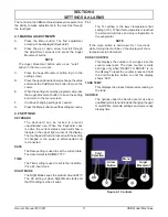
When the display reads “READY TO SERVE” the 
product is ready, pull the spigot handle open to 
serve.

3.6 REMOVING MIX FROM MACHINE

To remove the mix from the machine, refer to the follow-
ing steps:

A. 

Press the Cold Selection button until the display 
shows Motor On.

B. 

Drain the mix by repeatedly opening and closing 
the spigot. A container should be placed under 
the spigot to collect the liquid mix.

D. 

When the mix is drained, fi ll the tank with 1 gallon 
of cool tap water. After 30 seconds open the spigot 
to drain the water out of the machine.

C. 

Use Stera-Sheen or equivalent sanitizing solution 
according to manufacturer’s instructions to 
provide a 100 parts per million strength solution. 
Any sanitizer must be used only in accordance 
with the manufacturer’s instructions.

D. 

Pour the sanitizer into the tank.

E. 

After 5 minutes, drain the sanitizer out of the 
freezing cylinder.

F. 

Press the Auger Movement button to stop the 
auger. Press the Main Power Switch to turn the 
machine off.

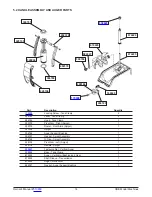
3.7 DISASSEMBLY OF MACHINE PARTS

Inspection for worn or broken parts should be made each 
time the machine is disassembled. All worn or broken 
parts should be replaced to ensure safety to both the 
operator and the customer and to maintain good machine 
performance and a quality product.

NOTE

The frequency of cleaning the machine and ma-
chine parts must comply with local health regula-
tions.

After the mix has been removed from the machine, follow 
the steps below to disassemble the parts.

A. 

Remove the spigot by pulling the pivot arms 
slightly outwards to disengage them from the 
handle knobs.

NOTE

Pull both arms at the same time to prevent them 
from twisting and breaking.

B. 

Remove the spigot handle by tilting it back and 
pulling upwards.

C. 

Remove the rosette cap.

D. 

Remove the tank fastening knobs from the tank 
clamps. Unclamp and remove the tank from the 
machine. Remove the gasket from the bottom of 
the tank. Remove the auger support and gasket 
from the tank.

E. 

Pull the horizontal auger towards the front of the 
machine to remove it. Remove the gear from the 
back of the auger.

F. 

Unscrew the fastening nut from the top of the 
vertical auger and remove the auger. Remove 
the gear from the bottom of the auger.

G. 

Remove the o-ring from the spigot assembly. 
Remove the o-ring by squeezing the it upward 
with a dry cloth. When a loop is formed, roll the 
o-ring out of the groove.

H. 

Remove condensate tray, drip tray and drip tray 
grid.

3.8 CLEANING AND SANITIZING THE 
MACHINE PARTS

Place all loose parts in a pan or container and take to 
the wash sink for cleaning. Local and state health codes 
dictate the procedure required. Some health codes require 
a four-sink process (pre-wash, wash, rinse, sanitize, and 
air-dry), while other codes require a three-sink process 
(without the pre-wash step). The following procedures 
are a general guideline only. Consult your local and state 
health codes for procedures required in your location.

A. 

Prepare Stera-Sheen or equivalent cleaner in 
2 gallons of 90° to 110°F (32° to 43°C) water 
following manufacturers instructions.

B. 

Prepare  sanitizing  solution  according  to 
manufacturer’s instructions to provide a 100 ppm 
strength solution. Mix the sanitizer in quantities 
of no less than 2 gallons of 90° to 110°F (32° to 
43°C) water. Check the strength of the sanitizing 
solution. Use a chlorine test strip and color chart 
to make sure the solution has 100 ppm.

C. 

Place all parts in the cleaning solution and clean 
the  parts  with  brushes and sponges.  Rinse  all 
parts with clean 90° to 110°F (32° to 43°C) water. 
Place the parts in the sanitizing solution.

D. 

Remove the parts from the sanitizing solution and 
allow them to air dry.

Summary of Contents for Stoelting CBB Series

Page 1: ...Model CBB OPERATORS MANUAL Manual No 513851 Rev 0 ...

Page 2: ......

Page 3: ...s built prior to date of change DO NOT ATTEMPT to operate the machine until instructions and safety precautions in this manual are read completely and are thoroughly understood If problems develop or questions arise in connection with installation operation or servicing of the machine contact Stoelting Stoelting Foodservice Equipment 502 Highway 67 Kiel WI 53042 1600 U S A Main Tel 800 558 5807 Fa...

Page 4: ...pecific safety information the following safety defini tions are provided to assist the reader The purpose of safety symbols is to attract your at tention to possible dangers The safety symbols and their explanations deserve your careful attention and understanding The safety warnings do not by themselves eliminate any danger The instructions or warnings they give are not substitutes for proper ac...

Page 5: ...utions 5 3 2 Operating Controls and Indicators 5 3 3 Assembly of Machine 6 3 4 Sanitizing 7 3 5 Freeze Down and Operation 7 3 6 Removing Mix From Machine 8 3 7 Disassembly of Machine Parts 8 3 8 Cleaning and Sanitizing the Machine Parts 8 3 9 Routine Cleaning 9 3 10 Preventative Maintenance 9 4 Settings Alarms 4 1 Making Adjustments 11 4 2 Settings 11 4 3 Alarms 12 4 4 Pressure Switch 12 5 Replace...

Page 6: ......

Page 7: ...ontrols to provide a uniform product They will operate with almost any type of commercial soft serve or non dairy mixes available including ice milk ice cream yogurt and frozen dietary desserts This manual is designed to help qualified service per sonnel and operators with the installation operation and maintenance of the CBB machines Figure 1 1 Model CBB116 37 ...

Page 8: ...th 11 27 9 cm height 28 71 1 cm depth 19 48 3 cm Weight 65 lbs 29 4 kg Electrical 1 Phase 115 VAC 60Hz running amps 10A connection type NEMA5 15P power cord provided Compressor 850 Btu hr Drive Motor 0 134 hp Air Flow Air cooled units require 10 air space on both sides and back Tank Volume 1 gallon ...

Page 9: ...claim for damages and or shortages in shipment with the carrier Stoelting Inc cannot make any claims against the carrier 2 3 MACHINE INSTALLATION Installation of the machine involves moving the machine close to its permanent location removing all crating set ting in place assembling parts and cleaning A Uncrate the machine B Remove the packing material and move the machine into place Do not lift t...

Page 10: ...isplayed in a 24 hour format G Press the Auger Movement button to save the value H Press the down arrow button to navigate to the NightModeoptionandpresstheAugerMovement Button I Set the On and Off settings as needed using the arrow buttons and Cold Selection button NOTE The On setting is the time when Night Mode be gins The Off setting is when Night Mode ends The settings are displayed in a 24 ho...

Page 11: ...ain electrical power has been disconnected Unplug the machine at the plug Do not pull the electrical cord to disconnect the machine from the power source H Donotoperateunderunsafeoperatingconditions Neveroperatethemachineifunusualorexcessive noise or vibration occurs 3 2 OPERATING CONTROLS AND INDICATORS Before operating the machine it is required that the op erator know the function of each opera...

Page 12: ...od processing equipment be certi fied for this use Use lubricants only in accordance with the manufacturer s instructions A Press the gear into bottom of the vertical auger andlubricatethegearteethwithsanitarylubricant Install the auger and secure it to the machine with the fastening nut B Press the gear onto the back of the horizontal auger Lubricate the gear teeth and the front of theaugerwithsa...

Page 13: ...ing solution Use a chlorine test strip and color chart to make sure the solution has 100 ppm Any sanitizer must be used only in accordance with the manufacturer s instructions B Pour the sanitizing solution into the tank C Press the Main Power Switch to turn the machine on Press the Auger Movement Switch to start the auger Make sure the display reads Motor On Check for leaks NOTE Make sure the dis...

Page 14: ...handle knobs NOTE Pull both arms at the same time to prevent them from twisting and breaking B Remove the spigot handle by tilting it back and pulling upwards C Remove the rosette cap D Remove the tank fastening knobs from the tank clamps Unclamp and remove the tank from the machine Remove the gasket from the bottom of the tank Remove the auger support and gasket from the tank E Pull the horizonta...

Page 15: ... kept clean at all times A mild alkaline cleaner is recommended Use a soft cloth or sponge to apply the cleaner B MONTHLY Air Cooled Condenser Cleaning A Disconnect power to the machine B The filter is attached to the rear by tabs in the rear panel Pressthetabsdownwardsandremovethe filter C Visually inspect the filter for dirt If it is dirty shake or brush the excess dirt off the filter and wash i...

Page 16: ...Owner s Manual 513851 10 CBB Model Machines ...

Page 17: ...y The touchpad will remain locked until the setting is changed or the power is disconnected and reconnected DATE The Date setting is used to set the current date The date format is DD MM YYYY TIME The Time setting is used to set to the local time It is a 24 hour clock NIGHT MODE The Night Mode keeps the product around 28ºF The On setting is when Night Mode starts and the Off setting is when it end...

Page 18: ... for 10 minutes to attempt to thaw the product After 10 minutes it will automatically restart Make sure there is a maximum of 1 gallon of mix in the tank 4 4 PRESSURE SWITCH Asolid light next to the Main Power switch indicates a high pressure condition in the refrigeration system Follow the instructions below to reset the pressure switch A Unplug the machine from the power source and remove the fi...

Page 19: ...al 513850 13 CBE Model Machines SECTION 5 REPLACEMENT PARTS Part Description Quantity 314227 Lid w Lock Tank 1 470741 Key Tank Lid 1 724059 Tank 1 396697 Gasket Tank 1 5 1 TANK AND COVER 470741 314227 724059 396697 ...

Page 20: ... 396766 Auger Support Bushing 1 396767 Gasket Spigot Assembly 1 396768 O Ring Spigot Assembly 1 428105 Pivot Arm Left Spigot 1 428106 Handle Spigot 1 538620 Fastening Nut Vertical Auger 1 556649 Base Tank Clamp 2 674224 Auger Vertical w Bushing and Gear 1 674225 Shaft Sleeve Transmission 1 674226 Auger Horizontal 1 684027 Gasket Auger Support Bushing 1 266186 266185 175558 556649 674226 428105 340...

Page 21: ... ǡ ȋ ǡ ǯ Ȍ ǡ ǡ ȋͳʹȌ ǡ Ȁ Ȁ Ǥ Ȁ ȋ Ȍ ǡ ǡ Ȁ ǡ ȋ Ȍ ǡ ȋ Ȍ ǡ Ȁ ǡ Ǥ ǯ Ǥ 4 Exclusions and Limitations ǡ Dz dzǡ ǡ Ǧ ǡ ǡ ǡ Ǥ AS IS ǡ ǡ ǡ ǡ ǡ Ǥ THE REMEDIES SET FORTH IN THIS WARRANTY SHALL BE THE SOLE LIABILITY STOELTING AND THE EXCLUSIVE REMEDY OF BUYER WITH RESPECT TO EQUIPMENT SUPPLIED BY STOELTING AND IN NO EVENT SHALL STOELTING BE LIABLE FOR ANY INCIDENTAL OR CONSEQUENTIAL DAMAGES WHETHER FOR BREACH OF WA...

Reviews: