


12
Bend
Reduction in maximum flue length for each bend
45
°
bend
1.0 metre
90
°
bend
1.0 metre
Reduction for bends
Part No.
Description
Length
0225805
Horizontal flue terminal
1.0 metre
0225810
Vertical flue terminal
1.0 metre
359
Twin adapter kit
N/A
0225770
Pitched roof flashing plate
N/A
0225765
Flat roof flashing plate
N/A
0225815
Condensate drain kit
N/A
0225820
0.25m extension (pair)
250mm
0225825
0.5m extension (pair)
500mm
0225830
1.0m extension (pair)
1000mm
0225835
2.0m extension (pair)
2000mm
0225840
45
°
bend (pair)
N/A
0225845
90
°
bend (pair)
N/A
0225850
Twin bracket (5)
N/A
0225855
Single bracket (5)
N/A
Twin flue accessories
MOUNTING THE BOILER
The fixing holes for the wall-mounting bracket should now
be drilled and plugged, an appropriate type and quantity
of fixing should be used to ensure that the bracket is
mounted securely. Once the bracket has been secured
to the wall, mount the appliance onto the bracket.
Pay attention to condense trap!
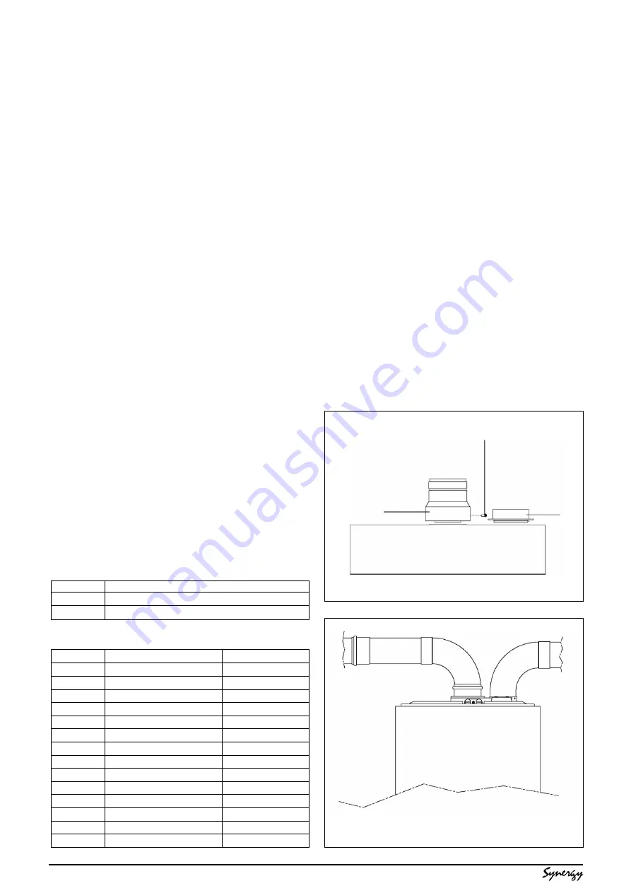
4.5.3.1 INSTALLATION OF TWIN ADAPTOR KIT (see
fig. 10 & 11)
●
Insert the exhaust connection manifold (A)
onto the appliance flue outlet.
●
Remove the blanking plate (located to the right
of the appliance flue outlet) and - using the
same screws - install the air inlet plate (B).
●
Using the hole in the exhaust connection
manifold as a guide, drill a 3mm hole in the
appliance flue spigot and secure the exhaust
manifold connection to the flue spigot using
the screw provided (C).
●
Using the two holes in the air inlet plate as a
guide, drill a 3mm hole in each and secure the
air inlet pipe/bend using the screws provided.
●
The twin flue pipes extensions and accessories
can now be installed by pushing together (the
plain end of each extension or bend should
be pushed approximately 50mm into the
female socket of the previous piece).
NOTE
When cutting an extension to the required length,
you must ensure that the excess is cut from the
plain end of the extension (see fig. 8). Remove
any burrs and check that any seals are located
properly.
You must ensure that the entire flue system is
properly supported and connected.
4.5.3
TWIN FLUE SYSTEM
The Vokera twin flue system enables greater flue
distances to be achieved (see 4.4.2) than that of
a concentric flue system. It can be used for
horizontal or vertical applications, however the
twin flue system must be converted to the
dedicated concentric flue kit for termination. It is
essential that the installation of the twin flue
system be carried out in strict accordance with
these instructions.
GUIDANCE NOTES ON TWIN FLUE INSTAL-
LATION
●
The flue must have a fall back of 1
°
back to
the appliance to allow any condensate that
may form in the flue system to drain via the
condensate drain. Consideration must also be
given to the fact that there is the possibility of
a small amount of condensate dripping from
the terminal.
●
Ensure that the entire flue system is
adequately supported, use at least one bracket
for each extension.
●
The entire flue system must be adequately
insulated to maintain heat within the flue
system thereby reducing the possibility of
condensate production.
●
As the exhaust outlet pipe can reach very high
temperatures it must be protected to prevent
persons touching the hot surface.
●
The condensate drain pipe must be connected
in accordance with building regulations.
Fig. 10
C
A
B
Fig. 11


