background image

HDSP-Series Operating Manual

21

Edition functions of the channels

HDSP-Series

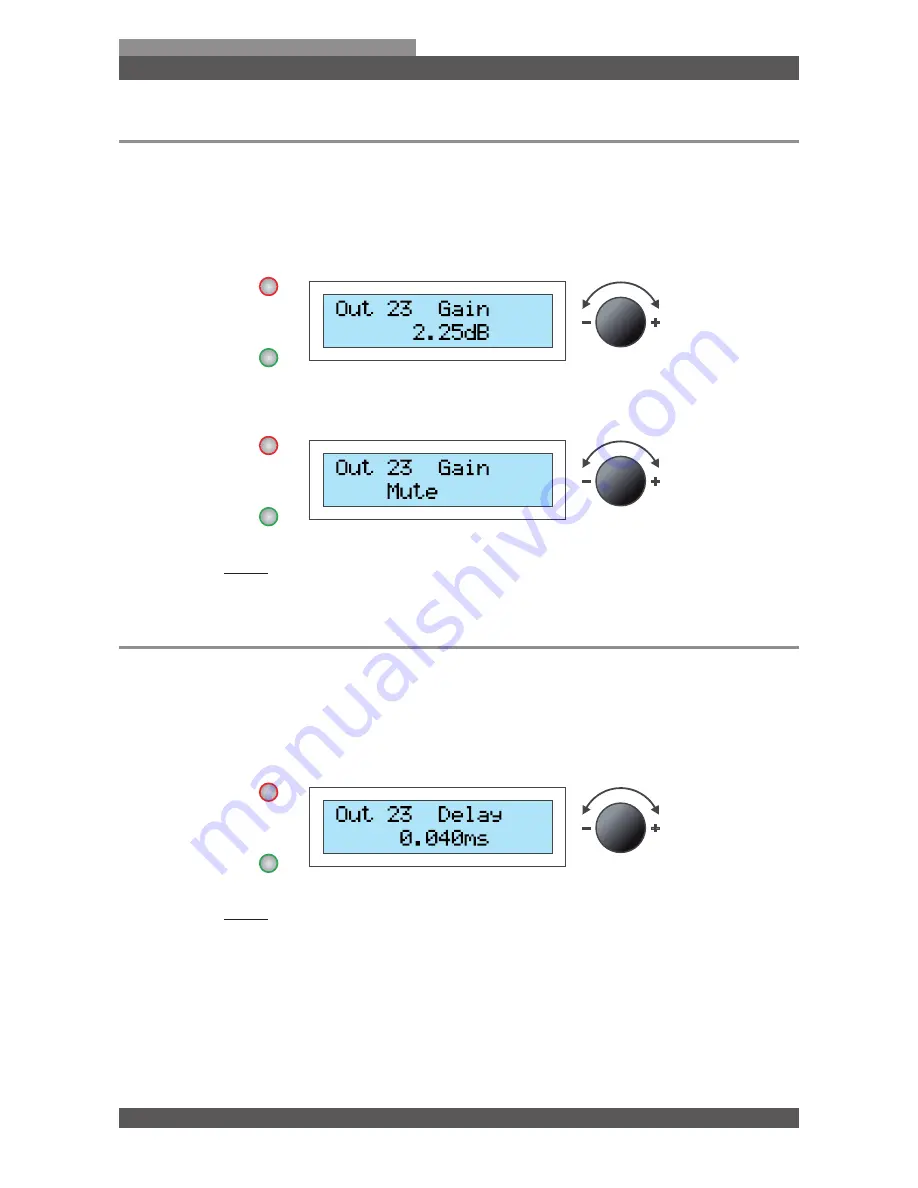
3.4 Gain (Input level and output level)

Here you can set the signal level (Gain) for the input and output channels.


Turn the 

Encoder wheel

 for setting the desired level.


■ Select within a range from 

-47.75 dB

 to 

12.00 dB

.


■ If you wish, you can switch the channel off by turning the 

Encoder wheel

 to 

Mute

.


■ Press the bottom


BUTTON

 to implement the change.

3.5 Delay

Here you can define the delay for the input and output channels.


■ Press the 

Encoder wheel 

to select from 

Feet

mm

 or 

ms.


Turn the 

Encoder wheel

 for setting the delay.


■ Press the bottom


BUTTON

 to implement the change.

Summary of Contents for HDSP-0.2A

Page 1: ...Operating Manual Voice Acoustic HDSP DSP Amplifier ...

Page 2: ......

Page 3: ...em menu 2 1 Browsing through the system menu 12 2 2 Menu tree 12 2 3 Preset Load 13 2 4 Preset Save 14 2 5 Access Level Password protection 15 2 6 Information 17 2 7 Routing 18 Part 3 Edition functions of the channels 3 1 Browsing through the channel menu 19 3 2 Menu tree 19 3 3 Link linking of channels 20 3 4 Gain Input level and output level 21 3 5 Delay 21 3 6 LowPass 22 3 7 HighPass 24 3 8 PEQ...

Page 4: ...all the power cable at places where it cannot be damaged especially at the sites of the socket extension cables and where it leaves the unit 09 The housing is designed for ventilation with air inlet and air outlet openings to protect the unit from overheating and ensure trouble free operation These openings must never be covered or closed The device may only be operated if sufficient ventilation i...

Page 5: ...s humidity maintenance not according to the prescribed intervals excessive dust or contamination powder of fire extinguisher operation with defective power aggregates operation with defective peripherals modification or modifications without the prior authorization by the manufacturer service by a non authorized worksite or normal wear The warranty is only applicable to the material and worktime f...

Page 6: ...ower 16 Ohm Technology Power Supply DSP Boards Class D Module Analog Input Digital Input Internal Presets Interface HDSP 12 12 16 000 W 4x 2 400 8x 800 9 920 W 4x 1 580 8x 450 4 800 W 4x 800 8x 200 Quad 4 8 4 4 x 80 Ethernet optional WLAN HDSP 6A 6 8 000 W 2x 2 400 4x 800 4 960 W 2x 1 580 4x 450 2 400 W 2x 800 4x 200 Dual 2 4 2 x 80 Ethernet USB optional WLAN HDSP 6D 6 8 000 W 2x 2 400 4x 800 4 96...

Page 7: ... connector for Audio output Each output is a symmetric XLR connector 04 Ethernet connection RJ45 jack for network connection The unit can be connected to the PC via a router with a 1 1 CAT 5 cable 05 Standard USB Jack Type B The unit can connected to the PC via a traditional USB cable 06 07 Speaker outputs The 4 pole Speakon sockets are double occupancy HDSP 3 6 12 HDSP 4 HDSP 2 HDSP 02 04 6 2 2 C...

Page 8: ...BU Each input is a symmetric XLR connector 04 Digital output 3 Pin connector for digital Audio output AES EBU Each output is a symmetric XLR connector 05 Analog input Separate 3 Pin connector for Audio input Each input is a symmetric XLR connector 06 Analog output Separate 3 Pin connector for Audio output Each output is a symmetric XLR connector 07 08 Speaker outputs The 4 pole Speakon sockets are...

Page 9: ...ctions 03 Button bottom EXIT To leave the system menu or the configuration functions 04 LCD Display Background lit double space 16 Segment LCD Display for all important edition parameters 05 Encoder wheel The encoder wheel is used for changing the parameter values By pressing you can select several para meter values and set these with a dial function 06 On Off switch The switch is only used to swi...

Page 10: ...iently which can lead to a reduction in the output power Therefore you should clean the filter at regular intervals Unplug the power connection to avoid the risk of electric shock Release the two screws on the front grille and remove the front grille Remove the filter foam and clean it with mild detergent under warm water Do not use the filter until after drying Mount the front grille with the two...

Page 11: ...signal processor Connect the device to the power supply The initialization process takes some minutes This time is re quired for starting up the unit During the initialization process all inputs and outputs are muted automatically in order to avoid undesired cracking sounds When the controller has started up it releases the programmed channels again and the name of the model and the most recent pr...

Page 12: ...p BUTTON you are guided thought the configuration functions Press the Encoder wheel for the desired configuration function To browse through the modules of the selected function turn the Encoder wheel Press the Encoder wheel for the selection of the module You can set the value in the module by turning the Encoder wheel To make modifications press the Encoder wheel Press the bottom BUTTON to leave...

Page 13: ...d 01 Preset ID You can select out of 80 internal presets 02 Preset designation You can designate a maximum of 16 characters View preset Turn the Encoder wheel for viewing the desired preset Press the Encoder wheel to select the preset Turn the Encoder wheel and select YES Press again and confirm the Encoder wheel The preset has been loaded now and is ready for operation ...

Page 14: ...eel to select the storage site Turn the Encoder wheel to select a character Press the Encoder wheel to confirm a character Modify characters Press the bottom button repeatedly until you have reached the character for modification Turn the Encoder wheel to select a new character Press the top BUTTON to confirm the designation Turn the Encoder wheel to select YES Confirm by pressing again the Encode...

Page 15: ...Locking the device Browse with the Encoder wheel to the module Locked Press the Encoder wheel to select the module Press the Encoder wheel to select a character The password must contain at least 8 characters Press the Encoder wheel to confirm a character Press the top BUTTON to confirm the password Save the password with the top BUTTON Now the device is protected with a password against improper ...

Page 16: ...ice Browse with the Encoder wheel to the module Unlocked Press the Encoder wheel to select the module Turn the Encoder wheel for selecting a character Press the Encoder wheel to confirm a character Press the top BUTTON to confirm the password Now the device is unlocked and you can make your settings ...

Page 17: ...HDSP Series 2 6 Information Here only information is displayed and no modifications can be made For viewing the information press the Encoder wheel VA Control Series number Firmware Version Hardware Version IP Address MAC Address Press the bottom BUTTON to leave the menu ...

Page 18: ...ettings to operate other speakers configurations For the implementation of a Voice Acoustic Set and the display of a preset speaker the router has already been determined and can not be altered in order to avoid the occurrence of faults Turn the Encoder wheel to select between Mono 3 Way or Stereo Sub Press the top BUTTON to confirm the selection Now the device is routed and you can make your sett...

Page 19: ...he channel for editing Press twice the Encoder wheel to select the channel Turn the Encoder wheel to search a channel function Press the Encoder wheel to view the channel function Turn the Encoder wheel to search a channel module in the function menu To make modifications press the bottom BUTTON Turn the Encoder wheel to select another function Press twice the bottom BUTTON to leave the menu 3 2 M...

Page 20: ...select the channel Turn the Encoder wheel and select ON Press the bottom BUTTON to implement the change Each modification of the parameters is transferred automatically to the linked channel Cancel linking Press twice the Encoder wheel Turn the Encoder wheel to search the channel canceling the linking Press the Encoder wheel and select the channel Turn the Encoder wheel and select OFF Press the bo...

Page 21: ...tting the desired level Select within a range from 47 75 dB to 12 00 dB If you wish you can switch the channel off by turning the Encoder wheel to Mute Press the bottom BUTTON to implement the change 3 5 Delay Here you can define the delay for the input and output channels Press the Encoder wheel to select from Feet mm or ms Turn the Encoder wheel for setting the delay Press the bottom BUTTON to i...

Page 22: ...within a range from 50 to 20 000 Hz If you wish you can switch the LowPass off by turning the Encoder wheel to Off Press the Encoder wheel to view the next module Set Filter Type Turn the Encoder wheel to search a filter Here you can select from 10 different filters BUT 6dB 12dB 18dB 24dB Butterworth 6dB 12dB 18dB 24dB BES 6dB 12dB 18dB 24dB Bessel 6dB 12dB 18dB 24dB LR 12dB 24dB Linkwitz Riley 12...

Page 23: ... functions of the channels HDSP Series Switching on and off crossover Turn the Encoder wheel to On for switching on the crossover Turn the Encoder wheel to Off for switching off the crossover Press the bottom BUTTON to implement all changes ...

Page 24: ... within a range from 20 to 20 000 Hz If you wish you can switch the HighPass off by turning the Encoder wheel to Off Press the Encoder wheel to view the next module Set Filter Type Turn the Encoder wheel to search a filter Here you can select from 10 different filters BUT 6dB 12dB 18dB 24dB Butterworth 6dB 12dB 18dB 24dB BES 6dB 12dB 18dB 24dB Bessel 6dB 12dB 18dB 24dB LR 12dB 24dB Linkwitz Riley ...

Page 25: ... functions of the channels HDSP Series Switching on and off crossover Turn the Encoder wheel to On for switching on the crossover Turn the Encoder wheel to Off for switching off the crossover Press the bottom BUTTON to implement all changes ...

Page 26: ...Encoder wheel for setting the desired frequency Select within a range from 20 to 20 000 Hz Press the Encoder wheel to view the next module Setting the EQ level Turn the Encoder wheel for setting the desired EQ level Select within a range from 12 00 dB to 12 00 dB Press the Encoder wheel to view the next module Setting the edge steepness Turn the Encoder wheel for setting the desired Q level Select...

Page 27: ...t from 8 different filters Bell Notch AllPass Low Shelf and High Shelf Band High Pass and Low Pass Press the Encoder wheel to view the next module Switching on and switching off the parameter filter Turn the Encoder wheel to On for switching on the crossover Turn the Encoder wheel to Off for switching off the crossover Press the bottom BUTTON to implement all changes ...

Page 28: ...ing the desired threshold value Select within a range from 48 00 to 24 00 dBu Press the Encoder wheel to view the next module Setting Attack Turn the Encoder wheel for setting the desired Attack Select within a range from 1 to 10 000 ms Press the Encoder wheel to view the next module Setting hold Turn the Encoder wheel for setting the desired hold time Select within a range from 1 to 10 000 ms Pre...

Page 29: ...xt module Setting the compression rate Turn the Encoder wheel for setting the desired compression rate Select within a range from 1 20 1 and 25 00 1 Turn the Encoder wheel to Infinite for a stepless compression rate Press the Encoder wheel to view the next module Setting the signal level Turn the Encoder wheel for setting the desired signal level Select within a range from 12 00 dB to 12 00 dB Pre...

Page 30: ... two modules Setting the threshold value Turn the Encoder wheel for setting the desired threshold value Select within a range from 48 00 to 24 00 dBu Press the Encoder wheel to view the next module Setting the release time Turn the Encoder wheel for setting the desired release time Select within a range from 1 to 100 dB s Press the bottom BUTTON to implement all changes ...

Page 31: ...ssional staff Open and close the device Unplug the power connection to avoid the risk of electric shock Release the 5 screws on the bottom of the unit Move the under floor slightly forward until it is out of the rear notch Use a small screwdriver to lift the under floor Remove the complete under floor After maintenance work assemble the unit in the reverse order ...

Page 32: ...ntinual improvement of product features For the safe operation of the unit this manual and all other required information must be available to all users at the time of assembly and disassembly of the unit and during operation Assemble or operate the unit only after reading and understanding this manual and keeping it at hand at all times at the site We are happy to receive your suggestions and pro...

Reviews: