11
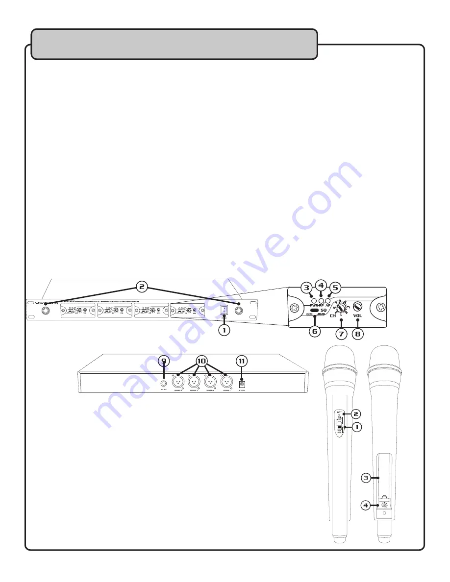
Descriptions and Functions
RECEIVER
1. Power –
This toggles power to the receiver ON/OFF .
2. Antenna Posts –
These are where the antennas are connected .
Note: Each antenna can go on either post.
CHANNEL MODULES
3. Power LED –
These indicate power to each of the modules .
4. RF LED –
These indicate microphone connection to each of the modules .
5. AF LED –
These indicate audio reception from each of the microphones .
6. SQ (Squelch) –
These toggle the threshold at which the module will receive audio . If the strength of the
signal being received is too low, it will not be heard .
• 0dB –
This means the threshold is low; meaning the range for the microphone is as far as it can be .
• -10dB –
This means the threshold is high; meaning the range for the microphone is as short as
it can be .
7. Channel Switch –
These allow the frequency of the microphones to be changed . There are 16 channels
to choose from .
8. Vol –
These adjust the output volume for each of the microphone channels .
9. Mixed Output –
This jack outputs all 4 microphone signals through a single ¼” unbalanced output .
10. Channel XLR Outputs –
These jacks output their respective channel audio through balanced XLR
outputs .
11. Power In –
This is where the included power adapter is connected .
MICROPHONE
1. Power Switch –
This toggles power to the microphone OFF/ON .
• MUTE – The middle position of the OFF/ON switch is the Mute function .
2. Power LED –
This indicates the status of the microphone .
• Green – Battery is full .
• Red – Battery is low and needs replacing .
3. Battery Compartment –
This is where the two AA batteries are installed .
4. Channel Switch
– This allows the frequency of the microphones to be
changed . There are 16 channels to choose from .
Rear Panel
Front Panel
Module
Summary of Contents for UHF-5816
Page 2: ......
Page 14: ...14 Notes ...
Page 15: ...15 Notes ...
Page 16: ...UHF 5816 Owner s Manual VocoPro 2015 v1 0 1015 www vocopro com ...


