12
DOC8003, Rev. B
March, 2003
Elite
Installation Manual
3.10
Connect the Electrical System
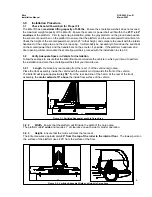
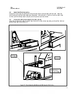
Plug in the two harness plugs to the winch unit. Plug in the optional pendant switch to the winch unit.
ENSURE THAT THE HARNESSES TRAVEL FROM THE DRIVE SCREW ASSEMBLY IN FRONT
OF THE TROLLEY TO THE PLUG ON THE WINCH! DO NOT ROUTE THE HARNESSES BEHIND
THE REAR OF THE TROLLEY UNIT OR THE HARNESS WILL BE DESTROYED WHEN THE
UNIT REACHES THE END OF ITS TRAVEL!
!
CAUTION!!
3.11
Platform Installation
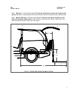
Using the remote control transmitter, or the pendant switch, run the unit “out” until it reaches
completely outside the vehicle and begins to extend the lifting mechanism down to the ground.
ONCE THE WINCH REACHES THE LIMIT OF ITS TRAVEL DOWN, STOP THE UNIT BY
RELEASING THE SWITCH! IF THE UNIT IS RUN CONTINUALLY ONCE THE PLATFORM HAS
REACHED THE GROUND, THE EXCESS TETHER WILL UNSPOOL AND COULD BECOME
ENTANGLED WITH THE INTERNAL MECHANISMS. STOP PRESSING THE DOWN BUTTON AS
SOON AS THE UNIT COMES TO REST ON THE GROUND!
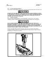
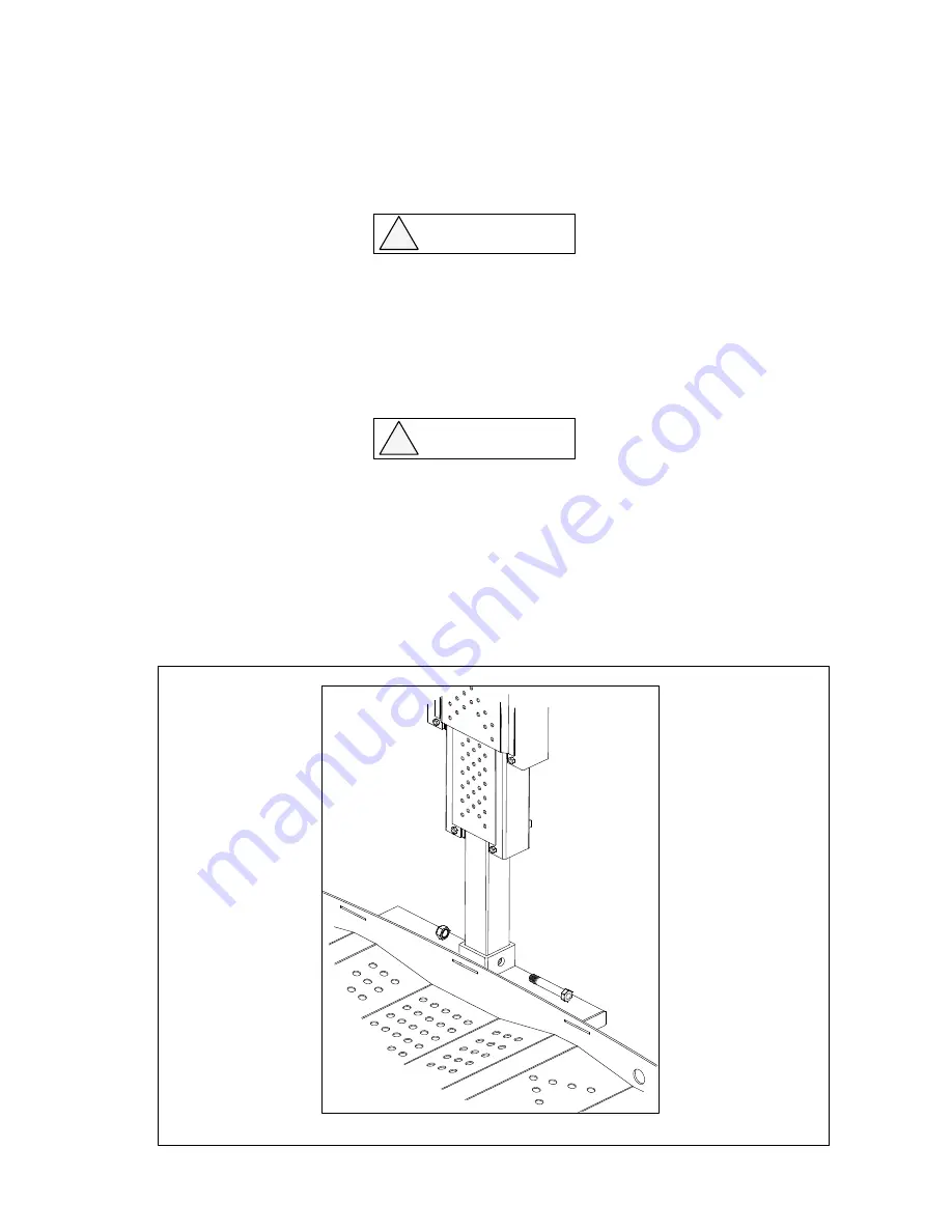
Position the welded platform assembly under the unit as shown and align the mast with the
gooseneck assembly. Place the 1/2”-13 bolt through the four holes as shown in Figure 3-8 below.
Tighten the 1/2”-13 Nylock nut completely.
!
CAUTION!!
Figure 3-8. Platform Installation


