Vixel InSpeed 375 User Manual Download Page 41

V

IXEL

 I

N

S

PEED

™ SAN S

TORAGE

 S

WITCH

 M

ODEL

 375

C

HAPTER

 3 S

WITCH

 M

ANAGEMENT

U

SER

S

 G

UIDE

EMBEDDED


IN


THE


FUTURE


OF


STORAGE

38

One-Step Zoning

Zoning allows ports to be divided into multiple virtual zones (or work groups), similar to Virtual 
Local Area Networking (VLAN). By separating activity on the network, zoning also eliminates 

change notification propagation (change notifications that occur within one zone cannot 
propagate to other zones.)

Use zoning to:

Separate different operating system environments.

Temporarily block or grant access during backup or other tasks.

Consolidate equipment logically.

Designate closed user groups for increased security.

Separate test or maintenance areas from production areas.

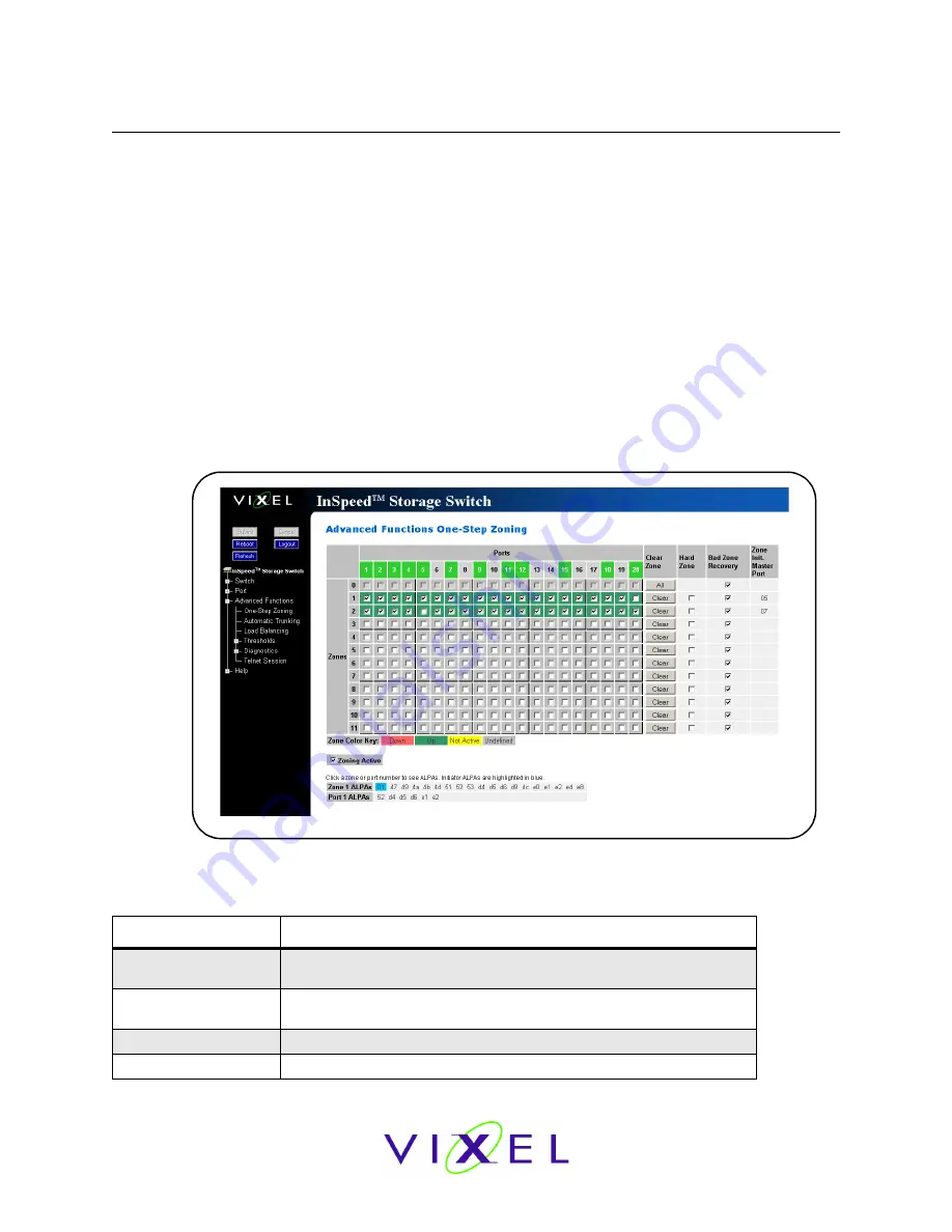
Zone configuration settings are available on the Web Manager’s One-Step Zoning page. The page 
is arranged as a grid of check boxes for placing ports in appropriate zones. Ports are listed across 

the top of the grid. Zones


are listed down the left side.


Similar to other Web Manager pages, the 

port color represents the current port status.

To view the One-Step Zoning page:

Click 

Advanced Functions > One-Step Zoning

.

The switch is capable of up to twelve zones. Initially, all ports reside in Zone 0. However, a port 
will clear from Zone 0 whenever it is selected and placed in another zone.
The color of each zone indicates its status. See the descriptions in the following table: 

Color

Description

Down (red)

One or more ports have been selected, zoning has been activated, but 
hardware has caused a failure.

Up (green)

Ports have been selected, zoning has been activated, and the FC-AL 
circuit is operational.

Not Active (yellow)

Ports have been selected but zoning has not been activated.

Undefined (gray)

No ports have been selected.

Figure 3-12: One-Step Zoning page

Summary of Contents for InSpeed 375

Page 1: ...embedded in the future of storage SAN Storage Switch USER S GUIDE InSpeedTM Model 375 For Apple Computer Users...

Page 2: ...of Vixel Corporation All other brand or product names referenced herein are trademarks or registered trademarks of their respective companies or organizations Vixel Corporation provides this manual a...

Page 3: ...IN THE FUTURE OF STORAGE ii Table of Contents 1 Introduction 1 2 Switch Installation 6 3 Switch Management 15 4 Technical Reference 57 Appendixes 61 A Specifications 62 B CLI Quick Reference 63 C Even...

Page 4: ...t around the InSpeed SOC 320 and is controlled by firmware loaded into the on board Flash The switch is designed as a central interconnect following the ANSI FC AL standard Devices are connected to th...

Page 5: ...monitoring and automatic bypass of problematic or unused ports Port Smart Settings which are predefined port level configurations that optimize switch performance and stability One Step Zoning includi...

Page 6: ...tached to separate servers which often results in difficult to manage multiple systems and trapped unused storage islands storage cannot be shared with other servers Benefits include Improved incremen...

Page 7: ...inance department Tape Library Consolidation Another switch application is the consolidation of multiple tape libraries attached to individual servers into a single library for all servers for backup...

Page 8: ...1 4 depicts a sample rich media configuration Server Clustering In this configuration the switch helps deliver improved application availability when combined with a server clustering software solutio...

Page 9: ...tatic bags returning the switch in any other container is not advised Make sure the following parts are included Switch unit RS 232 null modem serial cable Power cables 2 Self adhesive pads 4 Retentio...

Page 10: ...an equipment rack Contact a sales representative for more information or assistance in purchasing a kit UL Guidelines for Mounting Equipment in a Rack When installing equipment in a rack give careful...

Page 11: ...be facing downward 2 Place the washer on the screw prior to inserting the screw through the retention clip s mounting loop 3 Using a screwdriver tighten the screws to secure the retention clip to the...

Page 12: ...r Supply Fan LED a separate LED for each power supply fan module indicating the power supply fan module s status Ethernet LEDs The Ethernet LEDs indicate the network connection status Ethernet LEDs In...

Page 13: ...ered the Fault LED Regardless of the cause the switch requires immediate attention Power green LED When lit the switch is plugged in and the internal power supplies are functional 2 Gb s green LED Whe...

Page 14: ...e should be immediately replaced to maintain high availability Flashing Off Activity Data is being transferred between the port and device On Off Normal operation but no activity Port and device are f...

Page 15: ...on to indicate the device is ready to begin initialization To insert an SFP 1 Remove dust covers or plugs from the SFPs if provided 2 Slide the SFP into the port ensuring correct polarity until the la...

Page 16: ...the switch is operational the LEDs display current status as described in Switch LEDs on page 9 4 Power on any other switches connected to the SAN 5 For certain applications switch configuration must...

Page 17: ...er receptacle 3 Slide the safety latch over the power receptacle to expose the thumb screw 4 Loosen the two thumb screws No tools are required 5 Pull the unscrewed power supply fan module out of the s...

Page 18: ...itch information the event log port information and port diagnostics The switch incorporates two distinct interfaces for managing and monitoring purposes The Web Manager interface provides an intuitiv...

Page 19: ...wing serial port parameters Bits per second 19200 Data bits 8 Parity None Stop bits 1 Flow control None 3 If using HyperTerminal press ENTER to receive a prompt If using the tip command on a UNIX work...

Page 20: ...k the InSpeed Storage Switch menu item The Web Manager interface consists of a series of command buttons an expandable navigation menu and the displayed information area The command buttons and naviga...

Page 21: ...tation and firmware downloads To access product documentation 1 Click Help Documentation 2 Click Product Docs A documentation request web page appears 3 Enter the appropriate information and click Sub...

Page 22: ...ng the login request 2 Click OK The switch login page appears 3 Enter the switch s password The default password is password 4 Click Log In A message page appears while the page is loading If the page...

Page 23: ...date and time of the current host system appear in the New Date Time text box 2 Click Submit The new date and time appear under Current Date Time See Configuring Date and Time Settings on page 26 for...

Page 24: ...ing the Switch on page 48 To Click In this guide see View switch status InSpeed Storage Switch Viewing Switch Status on page 48 Change general switch configuration Switch Configuration Configuring the...

Page 25: ...settings may be changed to customize the switch to the network environment To make a change to the current switch configuration users must be logged in to the switch or know the switch password the sw...

Page 26: ...n or contact name 1 Click Switch Configuration 2 Enter the new value in the appropriate text box 3 Click Submit The Switch Configuration page displays the updated information Network Location The swit...

Page 27: ...The default setting is FF If other connected devices use the FF setting for another purpose select another Blocking ARB value for example FB Under normal circumstances this setting does not need to b...

Page 28: ...NMP Traps To configure an SNMP trap 1 Enter the Trap IP address for the device to which the trap information will be sent 2 Enter the Trap Port number This value is usually set to 162 for Windows and...

Page 29: ...the system clock will reset and the switch s date and time settings will be set to the host system s time settings of the next user to log in to the switch To change the time 1 Click Switch Date Time...

Page 30: ...t the password was saved and activated Opening a Telnet Session Some switch operations may require advanced features currently not found in the Web Manager These features are available in the Command...

Page 31: ...setting This setting is activated on the Port Smart Settings page CRC Error Threshold The maximum number of CRC errors allowed in a 10 second interval before a port is bypassed Setting this value to 0...

Page 32: ...assigned to each port and enables users to easily create and modify custom Smart Settings To view the Port Smart Settings page Click Port Smart Settings The Port Smart Settings page appears Expanding...

Page 33: ...e devices like JBODs SBODs tape drives or external RAID systems JBODs SBODs or tape libraries When a port is set to this Smart Setting change notifications are sent to other devices but change notific...

Page 34: ...ng 1 Select the desired Smart Setting from the list box 2 Click Set All 3 Click Submit to save the new settings Creating Custom Smart Settings In addition to the default Smart Settings users can creat...

Page 35: ...e list box 3 Select the new settings 4 Click Submit to save the new settings To rename a custom Smart Setting 1 Select the desired Smart Setting from the list box 2 Click Rename 3 Enter the new Smart...

Page 36: ...tree cascade configuration Setting Description Enable Policies Smart Insertion This policy is the default operating mode for all ports and determines what the switch looks for prior to allowing a port...

Page 37: ...bled the switch always generates a change notification to ensure the proper system updates are performed However when a device is removed for example an initiator or target the removal does not genera...

Page 38: ...ods include replacing the defective component cycling power to the device on the port removing and reinserting the bypassed port or cycling power to the switch Note This threshold setting can be adjus...

Page 39: ...specified email address If necessary download the latest switch firmware to the host system To load new firmware on the switch 1 Under Download New Alternate Firmware Version to Switch enter the dire...

Page 40: ...Enter the directory path and file name being sure to use a cfg extension 4 Click Save To load a saved configuration 1 Under Download New Configuration File to Switch and Reboot enter the directory pa...

Page 41: ...p Zoning page The page is arranged as a grid of check boxes for placing ports in appropriate zones Ports are listed across the top of the grid Zones are listed down the left side Similar to other Web...

Page 42: ...heck box 2 Click Submit To remove all ports from a zone 1 Click Clear at the end of the row of check boxes for the appropriate zone 2 Click Submit To remove all zones 1 Click All under the Clear Zone...

Page 43: ...3 15 depicts this type of zoning configuration In Figure 3 15 zone 1 includes ports 1 3 and 4 while zone 2 includes ports 2 4 and 5 Port 4 is in both zones Devices on ports 1 3 and 4 have direct acces...

Page 44: ...requires some coordination between the switches Building on the example for ports in multiple zones move the devices onto two switches and have the zones stretch between the two as in Figure 3 17 In...

Page 45: ...insert There is a secondary timeout the Bad Zone Recovery Delay Time that can also be configured The Bad Zone Recovery Delay Time causes a delay before ports are allowed to reinsert which prevents a h...

Page 46: ...rd Zones The limitations of Hard Zoning include 2 Gb of shared bandwidth over the entire Hard Zone Ports in a Hard Zone cannot use the Stealth Intelligent Change Manager Automatic Trunking and route b...

Page 47: ...ing Cascade Smart Setting To reduce contention and improve performance between initiator traffic and target traffic when using a string cascade configuration connect the ports of each switch together...

Page 48: ...ary trunk on a switch unless specified otherwise using the Load Balancing feature The primary trunk is always the lowest numbered port of any trunk group If the primary trunk fails the secondary trunk...

Page 49: ...ascade port 1 while host 2 uses cascade port 2 All traffic will use the lowest numbered primary cascade port by default but ports may be configured to use other cascades Load balancing configuration s...

Page 50: ...s overloaded If overloading occurs move one or more ports to a different trunk in the group To change the load balancing settings 1 Click a Trunk Group option to place a port into a specific trunk gro...

Page 51: ...it is operating normally Fault red one or more of the ports has failed the internal temperature has exceeded acceptable levels or another error has occurred Errors appear in the event log The switch w...

Page 52: ...ped operating Verify that the power supply fan module is properly seated in the switch Tip Rolling the mouse cursor over the port number displays the current port state Port Color Indication Green An...

Page 53: ...n page 66 To view the event log Click Switch Event Log The Event Log Messages page appears The last time the event log was polled appears at the top of the page To export the event log 1 Click Export...

Page 54: ...to easily identify attached devices when configuring load balancing Field Description Port Displays the current health of the port See Port Utilization and Health on page 45 for additional information...

Page 55: ...not The Port Utilization page displays each port s utilization percentage based on high average and low utilization To change the port utilization interval Click Advanced Functions Thresholds Switch S...

Page 56: ...been inserted into the network since the switch was reset or the counters were cleared CRC Errors Number of CRC errors that are detected in frames passing through this port since the switch was reset...

Page 57: ...ose device problems when a device is locked up or experiencing a high number of failures on a port To place a port into bypassed mode 1 Click Advanced Functions Diagnostics Port 2 Select the Bypass Po...

Page 58: ...o other data is being transmitted ARB FF ARB FF s are being transmitted to maintain link activity no other data is being transmitted ARB A port is arbitrating for network access to perform a task Read...

Page 59: ...et or is powering up Sometimes the port is sending this sequence to another hot cascaded switch like a new initiator being inserted in the network Change Notification A change notification has been de...

Page 60: ...hat the fiber cable is fully seated at either end If optical power meter is available verify the device is transmitting a signal If there is no signal present the device may require rebooting device d...

Page 61: ...d until rx_los is de asserted At that time the port insertion will be automatically retried The port continues to stay bypassed until the port can pass the port insertion criteria Tx_fault is asserted...

Page 62: ...tection Initiator Only Receive Changes Target Only Send Changes Off No Change Protection Switch Switch Send and Receive Changes Switch Switch Send and Receive Changes Switch Switch Send and Receive Ch...

Page 63: ...Channel Alan F Benner Fibre Channel McGraw Hill 1996 ISBN 0 07 005669 2 Tom Clark Designing Storage Area Networks Addison Wesley Longman 1999 ISBN 0 201 61584 3 Jan Dedek Fibre Channel The Basics ANCO...

Page 64: ...VIXEL INSPEED SAN STORAGE SWITCH MODEL 375 USER S GUIDE EMBEDDED IN THE FUTURE OF STORAGE 61 Appendixes...

Page 65: ...op and sides of the switch for proper air ventilation Do not place the switch on heat generating surfaces Operating conditions are listed below Number of Ports 20 Operating Rate All ports operate at 1...

Page 66: ...l session through a serial terminal emulation program such as HyperTerminal with the appropriate serial port for example COM1 and the following serial port parameters Bits per second 19200 Data bits 8...

Page 67: ...fic command Type command and press ENTER To save changes to the switch configuration at any time 1 Type save at any command prompt and press ENTER A message appears confirming the request 2 Type y and...

Page 68: ...4 types 5 add 6 view 7 edit 8 del 9 type 10 11 5 password 6 load 1 show 2 lbclr 3 delprt 4 addprt 5 delalpa 6 addalpa 7 ialpa 8 util 9 pu 1 10 pu 2 11 12 7 trunk 1 addprt 2 delprt 3 showmem 4 clr 5 6...

Page 69: ...ogress 3 CRIT Event failed with possible loss of integrity 4 ERR Condition failed action required 5 WRN Failed event occurred no action required 6 NOTIFY Configuration error or abnormal event occurred...

Page 70: ...Unknown event INFO 101 CRC detected on either an ISL LIP or Generic Frame NOTIFY 107 Trap task failed to update trap destination info CRIT 135 CLI level 1 password changed NOTIFY 136 CLI level passwo...

Page 71: ...8 D2 0D 13 80 38 56 35 63 99 D1 0E 14 7C 39 57 34 64 100 CE 0F 15 7A 3A 58 33 65 101 CD 10 16 79 3B 59 32 66 102 CC 11 17 76 3C 60 31 67 103 CB 12 18 75 3D 61 2E 68 104 CA 13 19 74 3E 62 2D 69 105 C9...

Page 72: ...operates over copper and fiber optic cabling at distances of up to 10 Kilometers It is unique in its support of multiple interoperable topologies including point to point arbitrated loop and switchin...

Page 73: ...port utilization 52 switch status 48 documentation 18 downloading firmware 36 E ethernet LEDs 9 event log 50 messages 66 F Fabric Connection Smart Setting 30 features switch 2 Fibre Channel references...

Page 74: ...hange notifications 34 creating 31 default 59 diagnostics 35 Fabric Connection 30 Initiator or Target 30 Initiator with Stealth 30 policies 33 port information 33 port recovery 34 pre insertion testin...

Page 75: ...tting started 16 hard zoning 43 initial switch setup 19 load balancing 46 loading firmware 36 network location 23 network settings 23 opening a telnet session 27 ordered sets 55 overview 17 password 2...

Reviews: