background image


  15/19 

Figure 15 - Network Settings page on Web Portal 

(VII)


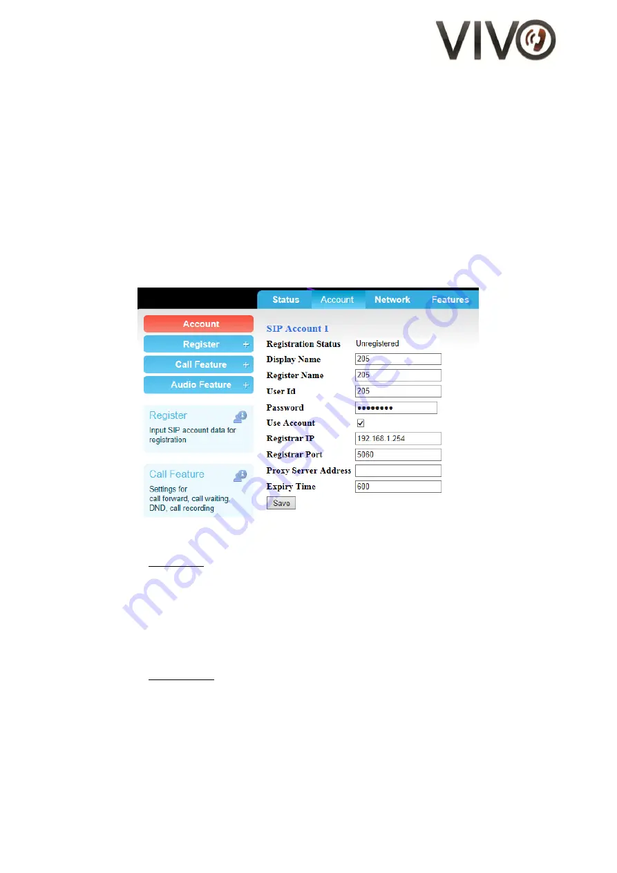
SIP Account Settings 

Parameters for Session-initiation-protocol (SIP) such as registrar address, proxy address, port etc. can 
be found in the "SIP Accounts" section on the Configuration page. 


1.


Go to Configuration page 

2.


On the left panel, click Register 

3.


A dropdown menu appears. Click on the "Account 1" link 

4.


Enter the SIP registration particulars for Account 1 


Note that you have the flexibility of registering to one server per account 

5.


When done, click 

Save


6.


The changes take effect immeidately 

7.


Complete the entries for Account 2 and Account 3 


Figure 16 - Account Settings page on Web Portal 


Parameters for Call settings for each account can be found under the title, "Call Settings", on the left 
panel.   
Such parameters include: 

-


Call Forward Mode 

-


Call Waiting activation / deactivation 

-


DND activation / deactivation 

-


Auto-Answer activation / deactivation 


Parameters for Audio settings for each account can be found under the title, "Audio Settings", on the 
left panel.   
Such parameters include: 

-


DTMF mode (in-band / RFC2833 / SIP INFO) 

-


Audio Codec preference (PCMU / PCMA / G.722 / G.729 / iLBC) 

-


ToS 

-


Jitter 


Summary of Contents for V656IP 1D WIFI

Page 1: ...N port for wired network connection LAN port for shared network access Codecs and Voice Features Wideband codec G 722 Narrowband codec G 711μ A ILBC Full duplex speakerphone with AEC Wi Fi Connectivity Max bandwidth 802 11n 150Mbps Max bandwidth 802 11g 54Mbps Max bandwidth 802 11b 11Mbps Average effective Range indoors 20 meters Average Transmission Power 12 5dBm Wi Fi Security standards WPA PSK ...

Page 2: ...and check for the following items enclosed a Main unit with hook switch and faceplate and overlay b Handset c Handset cord d RJ45 Ethernet cable e D C Power Adapter check with your vendor for this item may not be included 2 Connect the handset to the base unit using the coiled handset cord provided ...

Page 3: ...P 1D WIFI 3 Wait for approximately 25 seconds and the welcome screen comes up on the LCD 4 You have two options for the subsequent steps a WebPortal b LCD menu a By Web Portal i Press the OK button on V656IP 1D WIFI to find out its IP address ii Open a web browser and log in to the WebPortal of V656IP 1D WIFI iii Go to Network section iv Select Router mode for Net Operation Mode v Check the WIFI b...

Page 4: ...xt to Host SSID and choose the desirable one For Wi Fi hosts configured with hidden SSID check the Manual Input box and fill in the Host SSID field Figure 5 Screen capture of the Host SSID drop down box xv Fill in AP Password xvi Find the Save button at the bottom of the page and click on it xvii This will take you to the confirmation page Click Reboot xviii Disconnect the Ethernet patch cable xix...

Page 5: ... the WebPortal you will then see that the WIFI status shows it is Connected V656IP 1D WIFI has now been successfully configured as a Wi Fi client Figure 6 Illustration of V656IP 1D WIFI as a Wi Fi client Figure 7 Screen capture of the Network section showing WIFI connected successfully Wi Fi router ...

Page 6: ...e second softkey for alphabetical entry v Go to Network vi Go to item 16 WIFI vii You arrive at the WIFI menu Go to item 3 Host Scan viii Wait for several seconds to allow a complete search of all available Wi Fi connectivity ix Choose the desired one and press OK x Go to item 4 Host Encrypt Type on the WIFI menu xi Select the most appropriate one for the Wi Fi A P to which you attempt to connect ...

Page 7: ...nds on the Main Menu xvi Select Reboot xvii Press OK to confirm xxiii Disconnect the Ethernet patch cable xxiv Wait approximately 20 seconds and see that V656IP 1D WIFI acquires IP by DHCP xxv The screen of V656IP 1D WIFI returns to the ready state xxvi Press the OK button to read the IP address V656IP 1D WIFI has now been successfully configured as a Wi Fi client ...

Page 8: ...on to the WebPortal of V656IP 1D WIFI 2 Go to Network section 3 Select Router mode for Net Operation Mode 4 Fill in AP SSID AP Encrypt Type and AP Password 5 Find the Save button at the bottom of the page and click on it 6 This will take you to the confirmation page Click Reboot 7 Wait approximately 25 seconds and see that the LCD returns to the ready state V656IP 1D WIFI is now functional as a Wi...

Page 9: ... button at the bottom of the page and click on it 5 This will take you to the confirmation page Click Reboot 6 Wait approximately 25 seconds and see that the LED for MWI blinks twice 7 Plug in one end of the Ethernet cable to the laptop and another end to the WAN port of V656IP 1D WIFI labelled The Wi Fi connection is now shared with your laptop computer C Call Operation I Initiating a Call 1 Lift...

Page 10: ...b Portal go to Phone Settings page and adjust the volume settings see Figure 11 Figure 11 Phone Settings Page on Web Portal VI Call Flash If the call is on LINE1 1 During a conversation using the handset or the speakerphone press LINE2 button 2 The previous conversation is automatically put on hold 3 Listen for dial tone coming from the handset receiver or the speakerphone 4 To place another call ...

Page 11: ... but you can continue to hear from the other end 3 To deactivate Mute press the MUTE button again IX Call Waiting 1 During a conversation when there is an incoming call you will hear an alert tone An alert message will also display on the LCD 2 Press the 1st softkey to answer the incoming call 3 The previous party is put on hold automatically 4 To end the second call place the handset back on the ...

Page 12: ...Web Portal go to the Configuration page 2 On the left panel click on SIP NAT Settings link 3 Fill in any number of the entries for the 10 Memory keys 4 Remember to press save at the bottom of the page when you are done Figure 12 Memory Key and Mailbox Key setting on Web Portal ii To store mailbox message box number Memory Key 9 is reserved for message box mailbox number The standard faceplate has ...

Page 13: ...cess When prompt for login enter users for user name 1111 for password Users have limited functions and controls over the behavor of the phones Firmware upgrade SIP registry settings are not available to users III Administrator Access When prompt for login enter admin for user name admin for password Adminstrators enjoy full access to all configurations and actions important to phone settings Firm...

Page 14: ... masked To un mask simply un checked the mask password box Figure 14 Set Password for accessing the Web Portal VI Network Settings Administrators may choose to run V656IP 1D WIFI in either dynamic IP environment and static IP environment 1 Go to the Network page 2 Change network setting parameters 3 After making changes click save at the bottom of the page 4 A pop up window appears you may choose ...

Page 15: ...to one server per account 5 When done click Save 6 The changes take effect immeidately 7 Complete the entries for Account 2 and Account 3 Figure 16 Account Settings page on Web Portal Parameters for Call settings for each account can be found under the title Call Settings on the left panel Such parameters include Call Forward Mode Call Waiting activation deactivation DND activation deactivation Au...

Page 16: ...quired by the network environment in which the phone is deployed 1 Go to Configuration page 2 On the left panel click SIP NAT Settings 3 Scroll down to find NAT settings 4 When done with changes click Save 5 The changes take effect immeidately Figure 17 Memory key and NAT settings page on Web Portal ...

Page 17: ...uccessful File uploaded 8 The phone power cycles itself and comes back to run in the new firmware If the upgrade fails disconnect the base from the Ethernet and re connect it in order to trigger a power cycle Redo the firmware upgrade procedure Figure 10 Firmware upgrade User Configuration Backup Restore on Web Portal b Restore Default For various reasons including the need for having a clean slat...

Page 18: ...ECT REASSEMBLE CAN CAUSE ELECTRIC SHOCK WHEN THE APPLIANCE IS SUBSEQUENTLY USED 9 UNPLUG THIS PRODUCT FROM THE WALL OUTLET AND REFER SERVICING TO QUALIFIED SERVICE PERSONNEL UNDER THE FOLLOWINGCONDITIONS WHEN THE POWER SUPPLY CORD OR PLUG IS DAMAGED OR FRAYED LIQUID HAS BEEN SPILLED INTO THE PRODUCT IF THE PRODUCT HAS BEEN EXPOSED TO RAIN OR WATER 10 IF THE PRODUCT DOES NOT OPERATE NORMALLY BY FOL...

Page 19: ...19 19 HTI PRODUCT SUPPORT Should you need any technical assistance for this product please contact Hotel Technology International Limited Telephone 44 0 203 405 1200 Email office hotel tech com ...

Reviews: