background image

DU9800Z DLP Projector - User Manual 


34 

UM98001117EN00


Connecting Equipment 

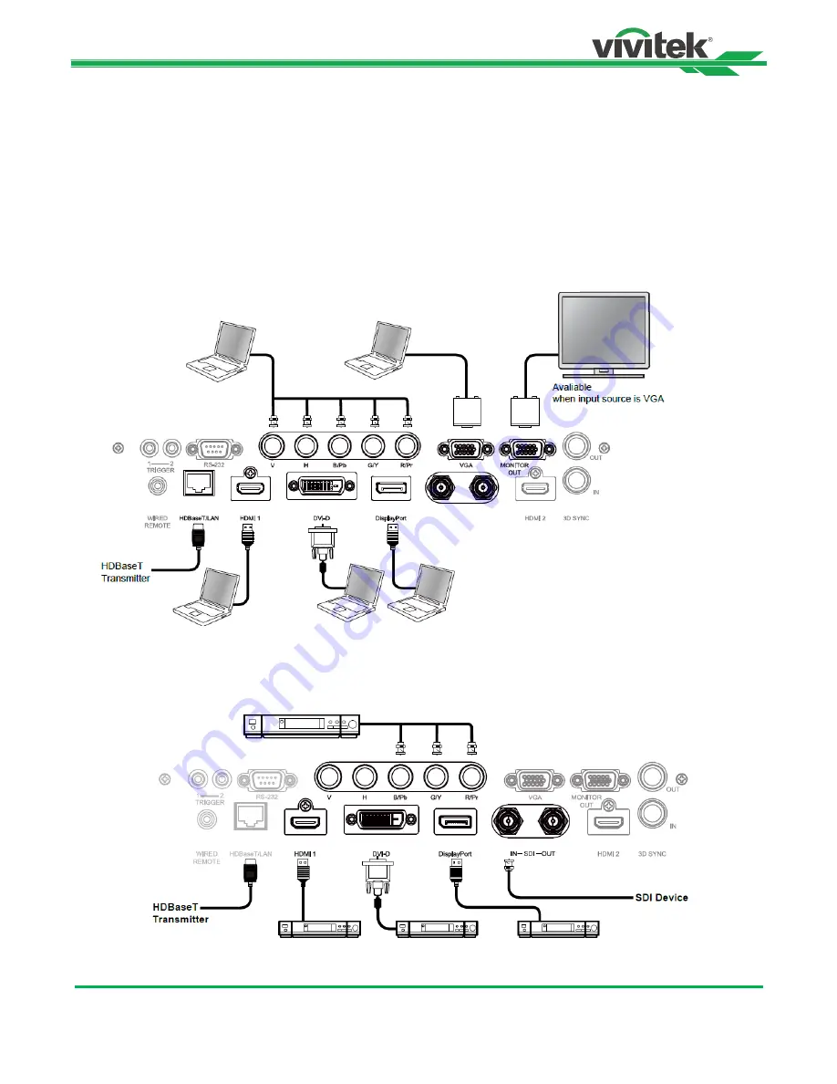
Follow the instructions below to connect the DU9800Z projector to a video source or external control equipment (if any). 
When connecting to the equipment, use the correct signal cable to connect to the signal source and ensure that the cable 
is securely connected. Fasten the nut on the joint and connect the signal source equipment to the projector according to 
the image below. 

Connecting a Computer 

Connect the PC signal to be projected to the projector through the DVI-D, HDMI, DisplayPort, VGA or RGBHV (BNC) 
cable. If the signal to be input is a VGA signal, connect the VGA cable to the external display to simultaneously monitor the 
projected content. 


Connecting a Video Device 

Connect video equipment to the input port of the projector via the DVI-D, HDMI and Component Video Connector. 


Summary of Contents for DU9800Z

Page 1: ...DU9800Z User s Manual User s Manual ...

Page 2: ...wer Supply 19 Turning On the Projector 19 Turning Off the Projector 20 Adjusting the Projection Mode 21 Adjusting the Projected Image Position 22 Adjusting the Focus and Zoom 22 Adjusting Geometric Distortion 23 Keystone 23 Rotation 24 Pincushion Barrel 24 Arc 25 Corner Adjustment 26 Preventing Unauthorized Use of the Projector 28 Using the Control Panel Lock 28 Using the Security Lock 29 Using Co...

Page 3: ...G Menu ALIGNMENT 48 OSD Menu CONTROL 51 OSD Menu SERVICE 54 Product Specification 55 Supported Signal Input Timing 56 Configurations of Terminals 59 DU9800Z Lens Series 60 Product Dimensions 61 LED Indication 62 Common Problems and Solutions 63 About the Vivitek Support 65 ...

Page 4: ...t provide any statement or warranty of the contents in the manual and clearly give up the implied warranties of merchantability and of fitness for a particular purpose The manufacturer reserves the rights to modify the publication and change the contents of the materials at any time without notice to any person About the Manual The manual describes how to install and use the projector and is appli...

Page 5: ...xpose user to a little lead a chemical known to the Stage of California resulting in risks of barrenness Please remember to wash hands after handling NOTIFICATION CANADA This Class A digital equipment complies with Canadian ICES 003 CE NOTIFICATION This is a Class A product which complies with rules for CE marking This product may cause radio interference that the user may be supposed to take adeq...

Page 6: ... of operation LASER LIGHT AVOID DIRECT EYE EXPOSURE Do not point laser or allow reflected laser light toward other people or reflective objects Direct or scattered light can be hazardous to eyes and skin There is a potential hazard of eye exposure to laser radiation if the included instructions are not followed Caution use of controls adjustments or performance of procedures other than those speci...

Page 7: ...getting into standby mode User should only use the connectors or accessories provided by the manufacturer 12 When user turns on the projector the red LED indicator would flash until stabilized Do not look at the lens directly while the projector is running 13 Unplug the power cord of the equipment if there is a thunderstorm or the equipment is not going to be used for an extended period of time 14...

Page 8: ...ime of printing The contents may be frequently updated due to the continuous product improvements and customer feedback You can find the latest version of the Manual and the manual of other Vivitek products on www vivitekcorp com Packing Checklist The following items are included in the packaging box of the DU9800Z series projector If there is any loss or damage to any item contact your dealer or ...

Page 9: ...gs see OSD controls 6 AC Power Switch Turn on off the AC power of the projector 7 AC Inlet Connect the supplied power cable to this inlet 8 I O Connector Panel Connect to various input control or output terminals to the projector 9 Lens Release Button Press the Lens Release button before removing the lens 10 Height Adjuster Adjust level of projector 11 Intake Vent The fans pull air to cool the rad...

Page 10: ... 14 Recess for projector handling These four recesses can be used for handling the projector Caution When installing ensure that you use only UL Listed ceiling mounts Contact your dealer for information on mounting the projector on a ceiling With ceiling installation use approved mounting hardware M6 screws maximum depth of screw is 16 mm ...

Page 11: ...ect an Ethernet cable Cat5 Cat6 not supplied from a computer network device or HDBaseT transmitter HDMI 1 Connect the HDMI cable from a computer or video device DVI D Connect to DVI D cable from a DVI D output of the device DisplayPort Connect the DisplayPort cable from a computer or video device SDI IN OUT Connect to SDI source HDMI 2 Connect the HDMI cable from a computer or video device 3D SYNC...

Page 12: ...NTER Use the button to select settings or confirm the changed settings EXIT Push the button to return to the menu on the previous level or exit the OSD menu CENTER LENS Push the button to center the lens and calibrate the parameter of lens shift Note The lens position needs to be calibrated for the accurate lens shift operation after installing the lens Please center the lens every time after the ...

Page 13: ...ens right or left ENTER Use the button to select settings or confirm the changed settings MENU Press the button to display or hide the OSD Menu EXIT Press the button to return to the previous Menu or exit the OSD Menu AUTO PC You can use this function to execute signal source auto synchronization BLANK Press the button to temporarily interrupt the projection STATUS Show OSD MENU SERVICE VGA Select...

Page 14: ...or resume the projection ID SET Set up ID number for remote control refer to the section Using Control ID for Multi projector Application Remote Control Operating Range The remote control uses the infrared transmission to control the projector It is not necessary to point the remote directly at the projector Provided you are not holding the remote perpendicular to the sides or the rear of the proj...

Page 15: ...ting turned on Certain high frequency fluorescent lights can disrupt remote control operation Be sure nothing obstructs the path between the remote control and the projector Do not expose the remote control to high temperature or humidity otherwise the remote control will not function correctly Battery installation instructions Make sure the battery is installed with the correct polarity Do not us...

Page 16: ... for information about mounting the projector on a ceiling Only use the projector on a solid and level surface Serious injury and damage can occur if the projector is dropped Caution Ensure that the hot air from the exhaust vent is not sucked into the projector Ensure the air intake and exhaust vents are unobstructed and keep the required distance from any object Below is required minimum distance...

Page 17: ...DU9800Z DLP Projector User Manual 16 UM98001117EN00 Mounting the Projector For mounting the projector please use UL Listed ceiling mounts and M6 screws maximum depth of screw is 16 mm ...

Page 18: ...power switch Do not touch the lens surface when removing or installing the lens Keep fingerprints dust or oil off the lens surface Do not scratch the lens surface Work on a level surface with a soft cloth under the projector to avoid scratchs or other damage If you remove and store the lens attach the lens cap to the projector to keep out dust and dirt Install New Lens 1 If the Lens cover is insta...

Page 19: ...rojector be sure to remove the lens cap from the back of the optional lens before installing the optional lens into the projector Failure to do so will cause damage to the projector and lens There is one safety switch inside the projector s lens slot to prevent unexpected injury by laser beam The projector cannot be turned on if the projection lens has not been installed or is not installed correc...

Page 20: ...tor is powered on correctly in order to avoid damage to components and un necessary wear and tear Refer to the following guide to power on the projector 1 Press the main power switch to the on I position as shown POWER LEDs will flash then turn a solid red 2 Press the POWER button on the control panel or ON button on the remote control 3 The Power LED and LIGHT LED flashes green until the power on...

Page 21: ... equipped with a power on switch and surge proector Do not turn off the AC power supply within 10 seconds after making adjustment or changing the setting Doing so is possible to cause loss of adjustments and settings and return to default Refer to the following guide to shut down the projector 1 Press the POWER button on the control panel or OFF button on the remote control once the Power Off wind...

Page 22: ...tallation orientation or viewing direction The selection options are described as below Auto Front Turn on the orientation sensor to change automatically the direction of the image Front Desktop Install the projector on the desktop and project the image forward Rear Desktop Install the projector on the desktop and project the image from the rear of the screen Front Ceiling Mount the projector on t...

Page 23: ...ctor is equipped with a safety switch inside the lens mount hole The projection lens must be installed in the projector before turning on the power or the projection can t be displayed There is a Lens Lock function on OSD menu to disable lens control adjustment for avoiding possible misoperation after you finish the adjustment Please make sure to disable the lock before performing the lens control...

Page 24: ...llustration is as below Horizontal Keystone 600 60 0 600 60 Vertical Keystone 400 40 0 400 40 Besides correcting H and V Keystone by separate you can use H and V keystone combination to correct the distortion In this case the effective range may be limited Note Above adjustable range is for the case you adjust single dimension the adjustable range of H and V Keystone combination is narrow if compa...

Page 25: ...that the image size is shrunk for projecting full image when Rotation is enabled please refer to below illustration for adjustable range 100 25 0 100 25 Pincushion Barrel When image is projected onto a cylindrical screen or hemispherical domes you can use Pincushion Barrel Correction to correct the distortion Use the or button to adjust Pincushion Barrel effect Keystone or rotate the image by Rota...

Page 26: ...when H or V Keystone is adjusted When rotation is adjusted the image size is shrunk to fit for the active display area Arc Besides correcting the pincushion or barrel effect ARC function allows you to correct the distortion on one edge You can seperatly correct the distortion on top bottom left or right of the image Please refer to below illustrations Top 150 30 0 150 30 Bottom 150 30 0 150 30 Rig...

Page 27: ...y occur due to the installation or projected surface In this case you can use Conner adjustment to correct the distortion corner by corner Please refer to below illustrations Top Left Corner Horizontal 192 Pixiels 0 192 Pixels Vertical 120 Pixiels 0 120 Pixels Top Right Corner Horizontal 192 Pixels 0 192 Pixels Vertical 120 Pixels 0 120 Pixels ...

Page 28: ...0Z DLP Projector User Manual 27 UM98001117EN00 Bottom Left Horizontal 192 Pixels 0 192 Pixels Vertical 120 Pixels 0 120 Pixels Bottom Right Horizontal 192 Pixels 0 192 Pixels Vertical 120 Pixels 0 120 Pixels ...

Page 29: ...hown as below if Control Panel Lock is turned on Select the OK button to confirm or Cancel to ignore the setting Once the Control Panel Lock is enabled all the control buttons on the projector are locked The below message is shown on the screen for several seconds if any control buttons are pressed Control Panel Lock is turned on OSD Settings Menu Position Menu Transparency Time Out 30 Seconds Mes...

Page 30: ...jector for preventing the unauthorized turning on the projector the setting is valid when you turn on the projector next time Enable the Security Lock Select CONTROL OSD Settings Security Lock then select On to enable the function as below illustration Once Security Lock is turned on the pop up message for setting up the password Lock as is shown as below Press arrow buttons to set up your passwor...

Page 31: ...jector can be unlocked from the OSD menu enter CONTROL OSD Settings Security Lock and select Off to disable Security Lock as the below illustration Once the Off option is selected the pop up window will be displayed to confirm the setting Select OK to disable the function otherwise select Cancel to ignore the setting Register Password Confirm Password Password Menu Cancel Password Menu Cancel OK C...

Page 32: ... number This option is available when Projector ID Control is turned on Set the identification number of remote control Press and hold ID SET button on the remote control around 5 seconds Power LED indicator is flashing red periodically Press two digits to set desired ID number each pressing shall be leisurely Power LED will flash on time when the remote control is confirmed the setting Press and ...

Page 33: ...ction is not enabled the number 26 is the current identification number of the remote control Note Project ID Control function is available when the option is turned on and remote control wire is not plugged into the wire remote jack port If ID Control Enable is set to Off the projector can receive any control signal from the remote control Even if the ID number is set into the remote control Mode...

Page 34: ...ct SETUP Light Power Light Power Change it to Custom Power Level with a value under 100 For example 90 or 85 The reduced power percentage will be used to later regulate the brightness when the Constant Brightness function is enabled 2 Enable the Constant Brightness function Note After a long period of time when a power boost reaches its limit of maximum power the Constant Brightness function will ...

Page 35: ...nnected Fasten the nut on the joint and connect the signal source equipment to the projector according to the image below Connecting a Computer Connect the PC signal to be projected to the projector through the DVI D HDMI DisplayPort VGA or RGBHV BNC cable If the signal to be input is a VGA signal connect the VGA cable to the external display to simultaneously monitor the projected content Connect...

Page 36: ...If the projector cannot receive the IR signal from the remote control due to the overly long distance or obstacles you can connect the cable to the IR remote control or the external IR transmitter optional via the WIRE input port to expand the working range of the remote control 3D Sync Out In Connect to 3D IR sync signal transmitter or device Note When the terminal of the remote control cable is ...

Page 37: ...jection screen and other 12V trigger device you can connect these devices to the projector s 12V trigger output port to configure the 12V signal settings The projector will output 12V signals when it s turned on You can use the signal to control the screen or device by turning on the OSD option under CONTROL Trigger 1 or Triger 2 ...

Page 38: ...ts the video signal R 232 IR remote control and the reception of the network control signals but do not support Power over Ethernet PoE The baud rate will be switched to 9600 automatically If RS232 command is sent via external HDBaseT transmitter If the command is sent via the HDBaseT transmitter the longest transmission distance is 100 meters If the transmission distance exceeds 100 meters there ...

Page 39: ...n on the OSD control panel or remote control There are five folders on the menu Press the or buttons to move through the submenus or secondary menus 2 Press the or button to select the option and or button to change values for settings Press to confirm the new setting 3 Press RETURN to leave a submenu or MENU to close menu Input Selection HDMI 2 PIP Off HDMI 2 Auto Source Off Color Space Auto Aspe...

Page 40: ... PIP Option PIP Input Position Auto Source Off On Color Space Auto YPbPr YCbCr RGB PC RGB Video Aspect Ratio 5 4 4 3 16 10 16 9 1 88 2 35 Letterbox Source Native Overscan Off Crop Zoom VGA Setup H Total H Start V Phase V Start Test Pattern Crosshatch Color Bar Checker Board H Burst V Burst White Red Green Blue Black 3D 3D Format Eye Swap DLP Link Dark Time Sync Delay Sync Reference Auto Sync Execu...

Page 41: ...on Gain Hue Saturation Gain Hue Saturation Gain Hue Saturation Gain Hue Saturation Gain Hue Saturation Gain Red Gain Green Gain Blue Gain Dynamic Black Off On Light Off Timer Disable 0 5 1 0 1 5 2 0 3 0 4 0 seconds ALIGNMENT Lens Lock Off On Lens Control Zoom Focus Lens Shift Lens Memory Load Memory Save Memory Clear Memory Center Lens Execute Digital Zoom Digital Zoom Digital Pan Digital Scan Res...

Page 42: ...se Chinese Simplified Chinese Traditional Japanese Korea Projection Mode Front Desktop Front Ceiling Rear Desktop Rear Ceiling Auto front High Altitude On Auto Auto Power Off Off On Auto Power On Off On Network Network Model Standby Power DHCP IP Address Subnet Mask Gateway DNS Mac Address Projection Control Service Off On Off On Light Power Light Power Custom Power Level Constant Brightness Eco N...

Page 43: ...98001117EN00 Time Out Message Box Keypad lock Security Lock SERVICE Model Serial Number Software Version 1 Software Version 2 Control Remote ID Active Source Signal Format H V Refresh Rate Pixel Clock Light Time Thermal Status Factory Reset ...

Page 44: ... the sub picture By choosing Off PIP function will be disabled and only one picture window will be projected PIP Input Press ENTER to display available sources for the sub picture and then select a source Note The unavailable input sources of sub menu will be grayed out and cannot be selected The available input source of the sub picture is outline in the below chart Main Picture VGA Component HDM...

Page 45: ... 255 255 255 RGB if an 8 bit image is used RGB Video Use the RGB color space and set the black to 16 16 16 RGB while set the white to 235 235 235 if an 8 bit image is used to correspond to the luminance value defined in the digital component standard Aspect Ratio This function allows the user to adjust the aspect ratio of the projection image by the or button Overscan Noise may appear on the edge ...

Page 46: ...lable options are 0 65ms 1 3ms and 1 95ms Sync Reference The projector provides DLP Link and 3D IR sync for 3D display you can specify the built in DLP Link or external 3D IR transmitter to synchronize the signal of the 3D glasses or select Auto to set the sync signal depended on the 3D format and if external 3D sync device is connected This function is only applied to the condition that 3D Format...

Page 47: ... the or button to adjust the level of hue Sharpness Press ENTER and use the or button to adjust the sharpness which changes the high frequency details Color Temperature The default of color temperature is Native and it is suitable for most situations As color temperature rises the picture will appear bluer while as the color temperature decreases the picture will appear redder The available option...

Page 48: ... These three options are used to increase or decrease the range of color input for the entire image If minimal amount of red green or blue appears in the gray areas lower the gain of the corresponding color accordingly As gain increases the contrast of the image will become lower HSG HSG is a function to adjust Hue Saturation and Gain independently it allows for specified color adjustments that ar...

Page 49: ...cus and horizontal shift of the lens Lens Memory This projector supports Lens Position Memory LPS Up to 10 programmed lens positions can be stored in the projector s memory You can load the stored memory settings to set up the lens position automatically Load Memory Use the or button to select the desired memory setting then press ENTER button to execute the lens setting the projector will adjust ...

Page 50: ...eft Corner Press the or button to correct the distortion at top left of the picture Top Right Corner Press the or button to correct the distortion at top right of the picture Bottom Left Corner Press the or button to correct the distortion at bottom left of the picture Bottom Right Corner Press the or button to correct the distortion at bottom right of the picture Blanking This function can adjust...

Page 51: ...jecting White the area where the two images overlap is projected twice the projectors white output levels The solution is to adjust the White Level First make sure that the units connected to the projectors are outputting black Then increase the White Level Top Bottom Left and Right until the non overlap area s brightness matches the overlap area Black Level The purpose of Black Level is to increa...

Page 52: ...he Auto option is set to AUTO then the system can adjust automatically to corresponding settings that are based on an estimated altitude If you prefer to manually set this feature you can select On or Off Off Turn off High Altitude mode if the projector is installed in an area under 4000 feet On Turn on High Altitude mode if the projector is installed in an area over 4000 feet Auto Set up this mod...

Page 53: ...button to select the number in the address to change Use the or button to increase or decrease the number in the IP address Network IP Address 172 xxx xxx xxx Subnet Mask Set the subnet mask The input method is the same as the setting for IP address Gateway Set the gateway The input method is the same as the setting for IP address DNS Set the DNS The input method is the same as the setting for IP ...

Page 54: ...e screen would be automatically turned on as well There is a 2 3 second delay to activate this function The selectable aspect ratios are as follows Off Turn off screen trigger 5 4 Outputs 12V of power on Trigger when Aspect Ratio is set to 5 4 4 3 Outputs 12V of power on Trigger when Aspect Ratio is set to 4 3 16 10 Outputs 12V of power on Trigger when Aspect Ratio is set to 16 10 16 9 Outputs 12V...

Page 55: ...rrent picture Pixel Clock Displays the pixel clock of the current input signal Light Time Displays the accumulated time which the light source of the projector is used Thermal Status Displays the current status of the thermal management components Factory Reset Use this function to reset all the settings to factory default light time Model DU9800Z Serial Number C712XXXXX01322 Software Version 1 ME...

Page 56: ...cal 50 Horizontal 15 I O Connection Ports HDMI v1 4a x2 DisplayPort DVI D Component 5 BNC VGA In 3G SDI In Out RS 232 VGA Out 3D Sync In Out 12v Trigger x2 Wired Remote HDBaseT LAN Shared Projection Method Table Top Ceiling Mount Front or Rear Free Tilt Portrait Security Solutions Kensington Security Slot Security Bar Anti Theft Lens Screw Dimensions WxDxH 530 x 693 x 248mm 20 8 x 26 8 x 9 7 or 68...

Page 57: ...O 1280x720 35 53 47 95 57 99 O O O O 1280 x 768 47 78 60 00 79 50 O O O O 1280 x 768 60 29 74 89 102 25 O O O O 1280 x 768 68 63 84 84 117 50 O O O O 1280 x 800 49 70 60 00 83 50 O O O O 1280 x 800 62 80 74 93 106 50 O O O O 1280 x 960 60 00 60 00 108 00 O O O O 1280 x 960 85 94 85 00 148 50 O O O O 1280x1024 63 98 60 02 108 00 O O O O 1280x1024 79 98 75 02 135 00 O O O O 1280x1024 91 15 85 02 157...

Page 58: ...60 00 74 25 O O O O O O O O O 1080i 28 13 50 00 74 25 O O O O O O O O O 1080i 33 72 59 94 74 18 O O O O O O O O O 1080i 33 75 60 00 74 25 O O O O O O O O O 720p 37 50 50 00 74 25 O O O O O O O O O 720p 44 96 59 94 74 18 O O O O O O O O O 720p 45 00 60 00 74 25 O O O O O O O O O 1080p 26 97 23 98 74 18 O O O O O O O O O 1080p 27 00 24 00 74 25 O O O O O O O O O 1080p 28 13 25 00 74 25 O O O O O O O...

Page 59: ...080 60 00 1125 67 50 O O 120 1080p50 Top and Bottom 1920x1080 50 00 1125 56 25 O O 100 1080p59 Top and Bottom 1920x1080 59 94 1125 67 43 O O 120 1080p60 Top and Bottom 1920x1080 60 00 1125 67 50 O O 100 1080p50 Frame Sequential 1920x1080 50 00 1125 56 25 O O 100 1080p59 Frame Sequential 1920x1080 59 94 1125 67 43 O O 120 1080p60 Frame Sequential 1920x1080 60 00 1125 67 50 O O 120 1080p100 2 Frame ...

Page 60: ...een Input 10 GND 3 Blue Input 11 GND 4 N C 12 VGA_SDA 5 N C 13 H Sync 6 GND 14 V Sync 7 GND 15 VGA_SCL 8 GND 16 GND HDMI 19 pin Type A 1 T M D S Data 2 Input 11 Ground 2 Ground 12 T M D S Clock C Input 3 T M D S Data 2 Input 13 CEC 4 T M D S Data 1 Input 14 N C 5 Ground 15 SCL 6 T M D S Data 1 Input 16 SDA 7 T M D S Data 0 Input 17 Ground 8 Ground 18 P5V 9 T M D S Data 0 Input 19 HPD 10 T M D S Cl...

Page 61: ...uthorized Vivitek dealer for additional details Part Number Lens Name F Number Focal Length Zoom Ratio Screen Size Throw Ratio D98 0810 Ultra Wide Angle Lens 1 85 1 95 17 95 21 93mm 1 22 1 40 500 0 84 1 03 1 D98 1215 Short Throw Lens 2 18 2 66 25 69 33 22mm 1 3 1 40 500 1 2 1 56 1 D98 1520 Standard Lens 2 17 2 65 31 9 42 2mm 1 33 1 40 500 1 5 2 0 1 D98 2040 Long Throw Lens 2 17 2 64 42 6 84 8mm 2 ...

Page 62: ...DU9800Z DLP Projector User Manual 61 UM98001117EN00 Product Dimensions ...

Page 63: ...Cover is opened Check if the top cabinet is installed properly Red Cycles of 4 Cooling fan error Contact with your nearest authorized dealer or service center On Red System Error Contact with your nearest authorized dealer or service center Light Source LED LED Display Projector status Procedure Off Light source is off Flashing Green Projector is turning on Red Cycles of 6 Light source lit fail Co...

Page 64: ...gs on your notebook or desktop PC 2 Turn off all equipment and power up again in the correct order 3 Check if shutter is enabled Problem The image is blurred 1 Adjust the Focus on the projector 3 Performance Auto Sync on the remote control or projector 4 Ensure the projection distance is within the specified range 5 Check that if the projection lens is clean Problem The image is wider at the top o...

Page 65: ...lled properly improper lens installation may cause to lens cannot work normally Please follow the lens installation procedure to check again 2 Check if Lens Lock function is enabled locking the lens will disable all of lens adjustment functions 3 Perform Center Lens function to calibrate the Lens again 4 Replace the other lens to check the problem if the lens is available 5 Contact with service ce...

Page 66: ...rt tech support North America Vivitek Service Center 15700 Don Julian Road Suite B City of Industry CA 91745 U S A Tel 855 885 2378 Toll Free Email T services1 vivitekcorp com URL www vivitekusa com Asia and Taiwan Vivitek Service Center 5F No 186 Ruey Kuang Road Neihu District Taipei Taiwan 11491 Tel 886 2 8797 2088 ext 6899 Direct Tel 0800 042 100 Toll Free Email kenny chang vivitek com tw URL w...

Reviews: