background image

DH6671 DLP Projector - User's Manual

52

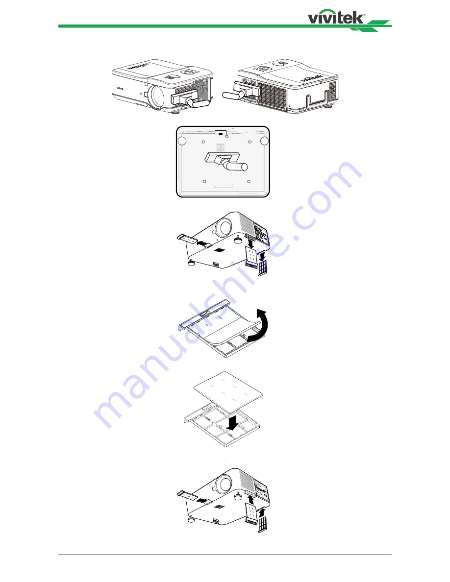
Refer to the following guide to clean the filters.

1. 

The left and rear filters can be cleaned as demonstrated in the following images.

2.  The rear exhaust vent can be accessed as shown.

!

3. 

Gently slide the filter holders in the direction shown as below.

!

4. 

Lift the filter foams from all three filter holders in the direction shown.Remove them    

  completely from each filter holder and discard.

!

5. 

Place a replacement foam and press down firmly

.

!

6. 

Replace the filter holders by pushing gently in the direction shown on below illustration

.

!

Summary of Contents for dh6671

Page 1: ...DH6671 User s Manual ...

Page 2: ...aution for Ceiling Mounting Installation 15 Upward or Downward Installation 16 Installing or Removing the Optional Lens 17 Installing the Optional Color Wheel 18 Remote Control and Operation Range 19 Turning On the Projector 20 Turning Off the Projector 21 Adjusting Projected Image Position 22 Adjusting the Focus and Zoom 23 Making Connections 24 Connecting to the Screen Trigger 26 Connecting to E...

Page 3: ...41 OSD Operation INSTALLATION 45 OSD Operation SERVICE 48 Maintenance 49 Replacing the lamp 49 Replacing the Lamp 50 Cleaning the Projector 51 Specification 53 Product Dimensions 54 Supported Signal Input Timing 55 Configurations of Terminals 56 DH6671 Lens Series 58 Troubleshooting 59 Indicator Messages 59 Common Problems and Solutions 60 About the Vivitek Support 62 ...

Page 4: ...es not provide any statement or warranty of the contents in the manual and clearly give up the implied warranties of merchantability and of fitness for a particular purpose The manufacturer reserves the rights to modify the publication and change the contents of the materials at any time without notice to any person About the Manual The manual describes how to install and use the DLP projector and...

Page 5: ...n radiate radio frequency energy and if not installed and used in accordance with the instruction manual may cause harmful interference to radio communications Operation of this equipment in a residential area is likely to cause harmful interference in which case the user will be required to correct the interference at his own expense CE NOTIFICATION This is a Class B product In a domestic environ...

Page 6: ...ace or other equipment that will generate heat including the amplifier 6 Use dry clothes to clean only 7 Do not obstruct any vent Carry out installation according to the guidelines of the Manufacturer 8 Do not destroy the safety protection function of polarized or grounding plugs A polarized plug has one wide and one narrow blade The grounding plug has two blades and one grounding blade The wide b...

Page 7: ...rsonnel to fine tune the edge blending brightness for multi projectors application With the lamp switching feature the projector can automatically select the lamps less used when turned on The projector has the replaceable color wheel and smart color wheel detection can automatically detect and switch the parameter of corresponding color wheels and can be used in conjunction with the color wheel o...

Page 8: ...Ԧ X O O O O O 䠁 Ԧ ᘛࡺ 䬌 䬌䪹ㅹ X O O O O O 䚕᧗ಘ X O O O O O ṏ 㚱㭺㚱 䈑峐ㆾ 䳈䘬 䦘 濌濪堐 ʹ烉堐䣢宍㚱㭺㚱 䈑峐军 宍悐ẞ䘬㝸ᶨ 峐㛸瀌 䘬 濌崭 SJ T11363 2006㞯Ⅾ奬 䘬旸濌天㯪ˤ 㲐烉戜Ḷ㫏䚇ᶶ ḶRoHS䘬澵 奬 炻㛔 㛢ṏ 䫎 㫏䚇RoHS 濶 䓝㮼ˣ䓝 学 旸 ἧ䓐㝸ṃ㚱 䈑峐 濶 㛔 堐 㞯㚱 X 䘬 㚱悐ẞ 㫏䚇ROHS 濶 孠瀃 䘬悐ẞˤ ὅ 㓧 搰 䓝 ᾉ ṏ 㰉㝻 䭉瀲 㱽炱 ⅷ 䓝 ᾉ ṏ 䍗 忈ㆸ䘬㰉㝻炻Ὣ徃 䓇ṏ 撨ⓖỶ㰉㝻䓝 ᾉ ṏ 炻ᾅ 䍗 Ṣỻ 炻ṭ ὃ㚱ℛ㛔ṏ 傥 㚱㚱㭺 㚱 䈑 峐 烉 悐ẞ 䦘 㚱㭺㚱 䈑峐ㆾ 䳈 烉堐䣢宍㚱㭺㚱 䈑峐 宍悐ẞ 㚱 峐㛸瀌 䘬 濌 SJ T11363 2006㞯Ⅾ奬 䘬旸濌天㯪ẍᶳˤ AC power cord For China VGA signa...

Page 9: ... hole The anti thief screw can be fasten to prevent Lens removing 9 Height Adjuster Adjust level of projector 10 Intake Vent filter The fans pull cool air to the projector for system cooling 11 I O Connector Panel Connect to various input control or output terminals to the projector 12 Rear IR Receiver Receives for IR signals from remote control 13 Rear Intake Vent filter Rear cooling intake do no...

Page 10: ...DH6671 DLP Projector User s Manual 10 Bottom View 109 84 ...

Page 11: ...display OSD or exit the OSD menu Up Down Left Rignt Cursor Use the buttons to navigate the OSD or select the OSD option ENTER Press the button to select or change settings in the OSD CANCEL Exit the OSD menu Power Press the button to turn the projector on main power switch must be turned on first or press to place the projector at standby mode SOURCE Select the input source AUTO Auto Sync to optim...

Page 12: ...t Connect to a monitor to display the projected content BNC R Pr G Y B Pb H V Connect RGBHV or Component signal from computer or component video enabled device Remote Connect the remote to the projector COMPONENT Connect a component video cable from a video device to the RCA jacks Video In Connect a composite video cable not supplied from a video device to the yellow RCA jack S Video Connect a com...

Page 13: ... OSD cursor down 13 LEFT Move OSD cursor right or enter submenu 14 ENTER Freeze unfreezes the projected image picture 15 MENU Display OSD main menu 16 RETURN Return to last OSD page or exit menu 17 INPUT Select the input source 18 PICTURE Display picture menu 19 NETWORK Display network setting menu 20 AUTO Auto adjustment for phase tracking size position 21 ASPECT Set up aspect ratio of the projec...

Page 14: ...ure that the intake vents do not recycle hot air from the exhaust vent When operating the projector in an enclosed space ensure that the surrounding air temperature within the enclosure does not exceed operation temperature while the projector is running and the air intake and exhaust vents are unobstructed All added enclosures should pass a certified thermal evaluation to ensure that the projecto...

Page 15: ...ojector is correctly installed Generally the light source facing the screen should be reduced or eliminated as much as possible The contrast of the image will be obviously reduced if the light directly shines on the screen such as the beam from windows or the searchlight cast on the image The image may become faded and not bright The available installation options as below Desktop Front Install th...

Page 16: ...djusted to the corresponding speed in order to maintain proper operating temperature of the projector Incorrect Projection Mode setting may affect hot air exhausting from the projector the heat high temperature may cause the projector goes into system protection component damage or lamp damage Brightness decay of upward or downward installation is faster than desktop or ceiling installation Refer ...

Page 17: ...you remove and store the lens attach the lens cap to the projector to keep off dust and dirt Removing the Existing Lens 1 Press and hold Lens Release button rotate the lens counterclockwise The existing lens will be disengaged Installing New Lens 1 Align the symbol on the lens label with the symbol on the top of the body align to the center of the lens hole and pull in the lens Arrow Mark 2 Pull o...

Page 18: ...an occur if the projector is dropped Removing the existing color wheel 1 Remove the screws A on the lamp cover Lift the lamp cover in the direction of the arrow B B A Installing the new color wheel 1 Insert the new color wheel 2 Unscrew the retaining screws x 4 on the color wheel 2 Tighten the 4 screws on the color wheel 3 Lift the color wheel in the direction shown 3 Place the color wheel A and t...

Page 19: ...erating Range The remote control uses infrared transmission to control the projector It is not necessary to point the remote directly at the projector Provided you are not holding the remote perpendicular to the sides or the rear of the projector the remote control will function well within a radius of about 10 meters 32 feet and 15 degrees above or below the projector level If the projector does ...

Page 20: ...able A Press the main power switch to the on I position as shown B the Power LED lights orange A B 2 Press the POWER button on the control panel or ON button on the remote control once the Power LED flashes green and the internal cooling fan starts 3 After approximately 10 seconds the Lamp1 and Lamp2 LEDs light green and the Power LED flashes more rapidly 4 Once the power LED is lit a solid green ...

Page 21: ... POWER button on the control panel or OFF button on the remote control once the Power Off window displays 2 Press the POWER button again on the OSD control panel or remote control to confirm power off The cooling fans continue to operate and the power LED flashes orange The cooling fans stop operating when the projector turns off 3 The projector enters Standby mode when the power LED lights orange...

Page 22: ...s shift The projected image can be moved up by 50 0 5V if the project is installed on the desk The projected image can be moved down by 50 0 5V if the project is installed via a ceiling mount Horizontal lens shift The image can be shifted horizontally to the right or left by 10 0 1H without moving the projector Vertical shift Projected image height 0 5 V Max 0 5 V Max IV Vertical shift Projected i...

Page 23: ...ol to adjust the focus or zoom effect using the increase and decrease buttons as required Control Panel Remote Control Displaying Test Pattern to Align the Projected Screen The built in test pattern is provided for installation and adjustment such as Crosshatch pattern You can select Test Pattern on OSD or TEST PATTERN button on the remote control to display the test pattern menu use or to select ...

Page 24: ... joint and connect the signal source equipment to the projector according to the figure below Connecting to Personal Computer You can connect the PC signal to be projected to the projector through the DVI D HDMI VGA or RGBHV BNC cable If the signal to be input is VGA signal connect the VGA cable to the external display to simultaneously monitor the projected content Connecting to the Video Device ...

Page 25: ...led by RS 232 command via connecting the projector to PC or control system through the standard 9 pin serial cable Refer to the Remote Communication Guide for detail information Wired remote control If the projector cannot receive the IR signal from the remote control due to the overly long distance or obstacles you can connect the cable to the IR remote control or the external IR transmitter opti...

Page 26: ...reen Trigger If your projection system includes the Electric projection screen and other 12V trigger device you can connect these devices to the Trigger and configure the settings on OSD The projector will output 12V signal when turning on the projector Screen ...

Page 27: ... do not support Power over Ethernet PoE Set the INSTALLATION RS232 Channel on the OSD menu to HDBaseT if you want to use the external HDBaseT transmitter to send the RS232 command to the projector via the RJ45 cable the baud rate will switch to 9600 automatically If the command is sent via the HDBaseT transmitter the longest transmission distance is 100 meters The projector may be interrupted or i...

Page 28: ...t the language to be used Selecting an Input Source The Input Source can be selected from the projector s control panel or from the remote control unit Refer to the following guide to select the Input Source 1 Press SOURCE button on the control panel or INPUT button on the remote control to display Input Selection Menu 2 Select the required source using or and press ENTER button to confirm the inp...

Page 29: ...Eco mode brightness may be affected Normal Mode 100 Brightness Eco Mode approx 80 Brightness Custom Power Level The adjustable range is 100 to 82 24 steps this option allows you to adjust lamp power by step Freezing a Picture The projected image can be frozen for short periods of time by using the remote control This feature is useful for capturing still images from movies or freezing an animation...

Page 30: ...ge is approximately 30 degree The following are conditions under which the maximum angle is achieved When the standard lens is used When the lens shift is set to the center point Image is projected in Wide mode Use or to select SETUP Keystone to enter Keystone menu Use or to select H Keystone or V Keystone to correct the distortion H Keystone Use to correct the distortion in horizontal direction V...

Page 31: ...ust define a keyword Locking the projector To setup the security keyword refer to the following guide 1 Press MENU on the OSD control panel on the projector or remote control to display the Main menu 2 Use arrow keys to select Security Lock under SETUP Advanced menu 3 Enter the password by remote control key and use to set up the PIN code 4 Once the PIN code is set the PIN code window is displayed...

Page 32: ...s of the projector status such as lamp status usage etc To access the Information refer to the following guide 1 Press MENU on the projector s OSD control panel or remote contro to display the Main Menu Scroll to the Installation Information menu using or and press 2 The Information menu is displayed as the default view The menu items in this screen are for display and cannot be modified 3 Press C...

Page 33: ...he following illustration shows the corresponding buttons on the remote control and on the projector 1 To open the OSD press the MENU button on the OSD control panel or remote control There are five folders on the menu Press the cursor or buttons to move through secondary menus 2 Press or to select menu items and or to change values for settings 3 Press RETURN to exit a submenu or to close menu ...

Page 34: ...300K Gamma 2 2 Film Graphic Video PC Auto Sync S Curve Advance Setting Input Balance Red Offset Green Offset Blue Offset Red Gain Green Gain Blue Gain HSG Red Green Blue Cyan Magenta Yellow White Noise Reduction Dynamic Black On Off Signal Input Selection VGA BNC DVI D Video S Video HDMI Component HDBaseT Auto Search On Off Auto Sync Adjust Always Auto Color Space Auto YCbCr YPbPr RGB PC RGB Video...

Page 35: ...et H V Alignment H Zoom V Zoom H Shift V Shift Reset 3D 3D Format Off Auto Side by Side Top Bottom Frame Sequential DLP Link On off 3D Swap Normal Reverse 3D 24Hz Display 96Hz 144Hz Filter Message Off 100 H 200H 500 H 1000H Filter Message Advanced Startup Logo On Off Remote Sensor Front Back Front Back HDBaseT Trigger On Off Control Panel Lock On Off Security Lock On Off Installation Projection Mo...

Page 36: ...hift Test Pattern Color Bar Cross Hatch Burst H Ramp Red Green Blue White Black Off Service Model Serial Number Software Version Source Information Active Source Pixel Clock Signal Format H V Refresh Rate Sync Type Sync Polarity Scan Type Video Type Lamp Status Lamp 1 On Off Lamp 2 On Off Usage Time Lamp 1 Life Remaining Lamp 2 Life Remaining Lamp 1 Time Lamp 2 Time Power On Time Filter Timer Rese...

Page 37: ...ightness Use or to increase or decrease the brightness of the image Contrast Use to adjust the contrast of the projected image Note The brightness and contrast controls affect each other To obtain the best setting fine tune of the brightness setting might be needed after adjustment of the contrast Saturation Use to adjust the saturation level of the color the higher the level the higher the satura...

Page 38: ...the image to correspond to the function that the projector uses for creation of the image S Curve S curve is to extend dynamic range while maintaining visual contrast this reduces contrast in highlights and deep shadows while maintaining or boosting it in middle tones Auto Sync Use this function to execute the Auto Sync for the input signal Input Balance There are two options for fine tuning Red G...

Page 39: ...Blue Cyan Magenta Yellow and white independently Noise Reduction Use to adjust the noise of the projected image This function is suitable for removing the noise of the image in interlaced scanning input Generally noise reduction can lower the value of the high frequency detail and make the image softer Dynamic Black Use the function to turn on off Dynamic Black it can be used to enhance the black ...

Page 40: ... HDBaseT transmitter Auto Search Use the function to turn on off Auto Search for the input source Auto Sync Adjust You can use this function to set auto synchronization for the input signal Auto The projector memorizes 10 sets of signal sources that you have used lately When the Auto option is selected the projector will choose the signal that you use last Always The auto sync function is executed...

Page 41: ... signal display Aspect Ratio This function allows the user to adjust the aspect ratio of the image Overscan Noise may appear on the edge of the projected image use this function to select Crop to hide the edge of the image or Off to display the original image Background Use this function to specify the image to be displayed on the screen when no signal is input You can select the Logo Blue or Blac...

Page 42: ...he lamp The projector will disable the lamp mode function highlighted every time when a switch is conducted till the switch of the lamp mode is completed The lamp mode options are not available before the switch of the lamp mode is completed receiver via control key button or RS 232 command Lamp Power Use the function to select Normal Eco or Custom Power Level mode Normal Projection is carried out...

Page 43: ...the projected image is enlarged Reset Set the Digital Alignment back to the factory default value H V Alignment H Zoom Use to narrow the horizontal size of the projected image V Zoom Use to narrow the vertical size of the projected image H Shift Use to move the narrowed projected image horizontally This function is only available when the projected image is narrowed V Shift Use to move the narrowe...

Page 44: ...sses for the left and right eyes are inverse set the 3D Swap to Inverse If the images are normal keep the current 3D 24Hz Display Set the 3D 24Hz image frame rate to 144fps or 96fps this option is only applicable when the input signal is 24Hz Note The projector provides DLP Link and 3D IR sync After the 3D Mode is enabled the built in DLP Link or external 3D IR transmitter can be used to synchroni...

Page 45: ...your local dealer if the projector will be installed upward or downward Standby Mode Use the to select standby mode to Normal or Network Standby Network Standby The projector maintains in the standby status at higher power 6W for the projector control via LAN In this mode the projector can be turned on via network control system Normal The projector maintains in the standby status at the lowest po...

Page 46: ...ommunication is connected select a suitable transmission rate Channel The RS232 control command can be sent to the projector through its RS 232 port the command can also be sent to the projector through the external HDBaseT transmitter to HDBaseT LAN terminal of the projector Set the following communication channels before sending the control command Local The RS 232 control command is sent throug...

Page 47: ...ojector several seconds to execute the change of the network setting till the following message disappears For more information about the network control connection and setting refer to Remote Communication Manual Lens Control Select this function to open the Lens Control menu for Zoom Focus or Shift adjustment You can use the Enter button to switch the Zoom Focus or Shift menu Use to adjust zoomi...

Page 48: ...ed remaining lamp1 life Lamp2 Life Remaining Display estimated remaining lamp2 life Lamp1 Time Display current lamp1 usage Lamp2 Time Display current lamp2 usage Filter Time Display the time from last reset of filter timer to now Power On Time Display the total Power On time of the projector Filter Timer Reset Reset filter timer please execute this function to synchronize the filter time display a...

Page 49: ... the Lamp Replacement section of this manual Continuous use of the lamp with LAMP 1 and or LAMP 2 lighted may increase the risk of lamp explosion A Lamp may explode as a result of vibration shock or degradation as a result of hours of use as its lifetime draws to an end Risk of explosion may differ according to the environment or conditions in which the projector and lamp are being used If a lamp ...

Page 50: ...o captive screws on the lamp module A Lift the module handle up as shown B A B 3 Pull firmly on the module handle in the direction shown to remove the lamp 4 Install the new lamp module s and re place the lamp cover 5 Tighten the two captive screws on the lamp module 6 Place the lamp cover and tighten one screw on the cover as below illustration A B ...

Page 51: ...ctly to the lens 2 Lightly wipe the lens in a circular motion Caution Do not use abrasive cleaners or solvents To prevent discoloration or fading avoid getting cleaner on the projector case Cleaning the Filters The projector uses three filters to keep the fans free of dust and other particles and should be cleaned every 500 hours of operation In dusty environments it is recommended to clean the fi...

Page 52: ...r exhaust vent can be accessed as shown 3 Gently slide the filter holders in the direction shown as below 4 Lift the filter foams from all three filter holders in the direction shown Remove them completely from each filter holder and discard 5 Place a replacement foam and press down firmly 6 Replace the filter holders by pushing gently in the direction shown on below illustration ...

Page 53: ...V 480i 576i EDTV 480p 576p HDTV 720p 1080i p I O Port HDMI v1 4a DVI D 3D Sync Out HDBase T LAN share with LAN control RGB In RGB Out Component YPbPr RGBHV Component RCA 3 Composite RCA Jack S Video Mini DIN 4pin RS 232 Screen Trigger Wire wired remote control USB for service Projection Method Desktop projection ceiling front or rear Size W x D x W 505x194x385mm excluding the protruding part Weigh...

Page 54: ...DH6671 DLP Projector User s Manual 54 Product Dimensions 508 389 208 389 ...

Page 55: ...0 768 60 59 87 V V V V V 1280 800 60 59 81 V V V V V 1280 800RB 120 119 9 V V V V V 1280 960 60 60 V V V V V 1280 1024 60 60 02 V V V V V 1280 1024 75 75 02 V V V V 1280 1024 85 85 02 V V V V 1440 900 60 59 887 V V V V V 1400X1050 60 59 98 V V V V V 1600 1200 60 60 V V V V V 1680 1050 59 94 59 94 V V V V V 1920 1200RB 60 59 95 V V V V V Video NTSC M 3 58 4 43 59 94 V PAL B G H I 50 V PAL N 50 V PA...

Page 56: ... T M D S Data 2 Input 11 Ground 2 Ground 12 T M D S Clock C Input 3 T M D S Data 2 Input 13 CEC 4 T M D S Data 1 Input 14 N C 5 Ground 15 SCL 6 T M D S Data 1 Input 16 SDA 7 T M D S Data 0 Input 17 Ground 8 Ground 18 P5V 9 T M D S Data 0 Input 19 HPD 10 T M D S Clock C Input 3D Sync Out 1 3 2 3D Sync Out 1 Signal 2 Ground 3 VCC 5V VGA D sub 15 pin 15 14 13 12 11 9 10 8 7 6 5 4 3 2 1 Input 1 Red In...

Page 57: ...creen Trigger Tip Sleeve Ring 1 Tip VCC 12V 2 Sleeve Ground 3 Ring Signal HDBaseT LAN Terminal RJ 45 8 7 6 5 4 3 2 1 1 TX 2 TX 3 TXC 4 Ground 5 Ground 6 RXC 7 RX 8 RX Wired Remote Tip Sleeve Ring 1 Tip VCC 3 3V 2 Sleeve Ground 3 Ring Signal ...

Page 58: ... 2 5 18 7 26 5mm 1 41 1 40 500 1 25 1 79 1 D88 ST001 Standard Lens 1 7 1 9 26 34mm 1 3 1 40 500 1 73 2 27 1 D88 SMLZ01 Semi Long Zoom 1 86 2 48 32 9 54 2mm 1 65 1 40 500 2 22 3 67 1 D88 LOZ101 Long Zoom 1 1 85 2 41 52 8 79 1mm 1 5 1 40 500 3 58 5 38 1 D88 LOZ201 Long Zoom 2 1 85 2 48 78 5 121 9mm 1 55 1 40 500 5 31 8 26 1 Above lenses can support to vertical shift 0 50 horizontal shift 10 except o...

Page 59: ...links 2 times The internal temperature is abnormally high The temperature around the projector are high use the projector in an environment with the temperature of lower than 104 F 40 C Air intake may be blocked relocate the projector to an area with proper ventilation Internal circuit may be fail contact the local Vivitek service center Lamp 1 Lamp 2 Off Lamp is turned off Green on Lamp mode is s...

Page 60: ...es and the problem remains put the original batteries back and go to the next step Keep a record of the steps you take when troubleshooting The information may be useful when call ing for technical support or for passing on to service personnel Image Problems Problem No image appears on the screen 1 Verify the settings on your notebook or desktop PC 2 Turn off all equipment and power up again in t...

Page 61: ...amp to turn off 3 Replace the lamp module Remote Control Problems Problem The projector does not respond to the remote control 1 Direct the remote control towards remote sensor on the projector 2 Ensure the path between remote and sensor is not obstructed 3 Turn off any fluorescent lights in the room 4 Check the battery polarity 5 Replace the batteries 6 Turn off other Infrared enabled devices in ...

Page 62: ...Europe Middle East and Africa Vivitek Service Support Zandsteen 15 2132 MZ Hoofddorp The Netherlands Tel 31 20 655 0960 Email support vivitek eu URL www vivitek eu China Vivitek Service Center 上海浦东世纪大道 1090 号斯米克大厦 18 层 1802 室 201209 Tel 400 888 3526 Toll Free Tel 021 58360088 142 Direct Email service vivitek com cn URL www vivitek com cn Asia and Taiwan Vivitek after sales service Vivitek Corporat...

Reviews: