background image

24

Installation Manual

7. Installation Manual

7.1 Choosing an Installation Site

    Before choosing the installation site,obtain user approval.

    Indoor unit


The indoor unit should be sited in a place where:

     1) the restrictions on installation specified in the indoor unit  installation drawings are met.

     2) both air intake and exhaust have clear paths met.

     3) the unit is not in the path of direct sunlight.

     4) the unit is away from the source of heat or steam.

     5) there is no source of machine oil vapour (this may shorten indoor unit life).

     6) cool(warm) air is circulated throughout the room.

     7) the unit is away from electronic ignition type fluorwscent lamps (inverter or rapid stert type) as they may shorten

the  remote controller  range.

     8) the unit is at least 1 metre away from any television or  radio set(unit may cause  interference with the picture or

sound).

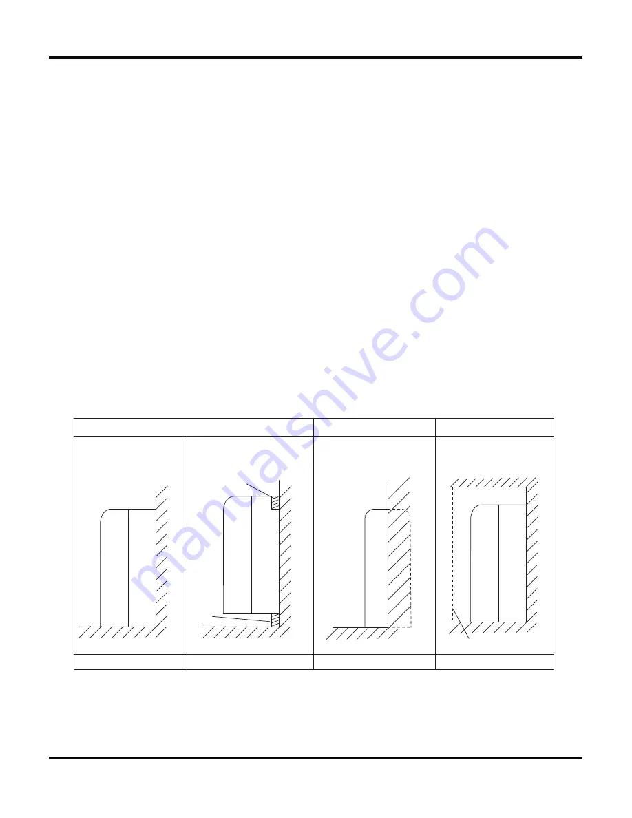
7.2  Indoor Unit Installation Drawings

The indoor unit may be mounted in any of the three styles shown here.

Exposed

Floor lnstallation

Wall Installation

Molding

Mounting plate

Half conceated

Concealed

Grid(field supply)

Summary of Contents for ACP-12CT35GECI

Page 1: ...ACP 12CT35GECI ACP 18CT50GECI Service manual ENG RoHS NNO 1 09 ...

Page 2: ......

Page 3: ...Electrical Wiring Part 5 Schematic Diagram 6 1 Remote Control Operations 6 2 Description of Each Control Operation Part 6 Function and Control Part 7 Installation Manual Table of Contents 5 3 Printed Circuit Board 7 1 Choosing an Installation Site 7 2 Indoor Unit Installation Drawings 7 3 Installation Tips 7 4 Indoor unit Installation 2 2 Operation Characteristic Curve 2 5 Noise Criteria Curve Tab...

Page 4: ...ation 40 9 3 Flashing LED of Indoor Outdoor Unit and Primary Judgement 40 9 4 How to Check Simply the Main Part 43 8 1 Indoor Unit 34 8 2 Outdoor Unit 36 Part10 Removal Procedure 48 10 1 Removal Procedure of Indoor Unit 48 10 2 Removal Procedure of Outdoor Unit 09K 12K 53 10 3 Removal Procedure of Outdoor Unit 18K 57 Table of Contents ...

Page 5: ...Summary and features 1 Summary and Features Indoor Unit ACP 12CT35GECI ACP 18CT50GECI Outdoor Unit ACP 12CT35GECI Remote control ACP 18CT50GECI ...

Page 6: ... be performed by your dea ler or a specialized subcontractor as there is the risk of fire electric shock explosion or injury Have all wiring connected tightly Loose connection may lead to overheating and a possible fire hazard Make sure the outdoor unit is installed on a stable level surface with no accumulation of snow leaves or trash beside Make sure the ceiling wall is strong enough to bear the...

Page 7: ...apacitor F Input of Heater W Evaporator Form Aluminum Fin copper Tube Pipe Diameter mm 6 35 Row fin Gap mm 2 1 2 Coil Length LXDXW mm 511X24X396 Swing Motor Model MP24AE Output of Swing Motor W 2 0 Fuse A PCB 3 15A Sound Pressure Level SH H M L SL dB A 42 40 38 37 35 32 26 Sound Power Level SH H M L SL dB A 52 50 48 47 45 42 36 Dimension WXHXD mm 700X600X215 Dimension of Carton Box L W H mm 785X68...

Page 8: ... F m m r e t e m a i D n a F 400 g n i t s o r f e D c i t a m o t u A d o h t e M g n i t s o r f e D 1 T e p y T e t a m i l C I n o i t a l o s I 4 2 P I n o i t c e t o r P e r u t s i o M Permissible Excessive Operating Pressure for the Discharge Side 8 3 a P M Permissible Excessive Operating Pressure for the Suction Side 2 1 a P M 2 5 A B d L M H l e v e L e r u s s e r P d n u o S 2 6 A B d...

Page 9: ...or Form Aluminum Fin copper Tube Pipe Diameter mm ĭ6 35 Row fin Gap mm 2 1 2 Coil Length LXDXW mm 511X24X396 Swing Motor Model MP24AE Output of Swing Motor W 2 0 Fuse A PCB 3 15A Sound Pressure Level SH H M L SL dB A 48 46 44 41 37 35 32 Sound Power Level SH H M L SL dB A 58 56 54 51 47 45 42 Dimension WXHXD mm 700X600X215 Dimension of Carton Box L W H mm 785X680X280 Dimension of Package L W H mm ...

Page 10: ...ut of Fan Motor W 60 Fan Motor RLA A 0 58 Fan Motor Capacitor ȝF Air Flow Volume of Outdoor Unit m3 h 3200 Fan Type Axial flow Fan Diameter mm ĭ520 Defrosting Method Automatic Defrosting Climate Type T1 Isolation I Moisture Protection IP24 Permissible Excessive Operating Pressure for the Discharge Side MPa 3 8 Permissible Excessive Operating Pressure for the Suction Side MPa 1 2 Sound Pressure Lev...

Page 11: ...t i c a p a RQGLWLRQV Indoor Û Û Indoor air flow High Pipe length 5m RQGLWLRQV Indoor Û Û Indoor air flow High Pipe length 5m 0 0 9 0 7 0 6 0 5 0 4 0 3 0 2 0 1 0 1 1 0 2 1 0 0 1 0 9 0 8 0 7 0 6 0 5 0 4 0 3 0 2 0 1 0 80 11 10 9 8 7 6 5 4 3 2 1 0 A t n e r r u 11 10 9 8 7 6 5 4 3 2 1 0 A t n e r r u RQGLWLRQV Indoor Û Û Outdoor Û Û Indoor air flow High Pipe length 5m RQGLWLRQV Indoor Û Û Outdoor Û Û...

Page 12: ...evolution rps Temperature condition ć Model name Standard pressure Indoor Outdoor P MPa T1 ć T2 ć 20 7 6 12k 2 2 to 2 4 70 to 35 2 to 4 Super High High 77 Temperature condition ć Model name Heat exchanger pipe temp Indoor fan mode Outdoor fan mode Compressor revolution rps Standard pressure Indoor Outdoor P MPa T1 ć T2 ć 27 19 35 24 18k 0 9 to 1 1 12 to 14 70 to 40 Super High High 70 Temperature c...

Page 13: ...L SL 46 47 48 49 50 51 52 15 20 25 30 35 40 45 50 55 60 65 70 75 80 85 Compressor frequency Hz Noise dB A Cooling Heating 30 0 40 0 50 0 60 0 15 20 25 30 35 40 45 50 55 60 65 70 75 80 85 90 94 Compressor frequency Hz Noise dB A Cooling Heating 45 46 47 48 49 50 51 52 53 1 2 3 4 5 6 7 8 9 10 11 12 13 14 15 16 17 Compressor frequency Hz Noise dB A Cooling Heating Indoor side noise when blowing Indoo...

Page 14: ...10 Constrction views 3 Construction Views 3 1 Indoor Unit Unit mm 700 215 600 398 205 22 ...

Page 15: ...11 Constrction views 364 930 896 695 396 560 368 730 3 2 Outdoor Unit 09K 12K Unit mm 18K Unit mm 848 320 540 540 766 276 286 ...

Page 16: ...RATOR HEAT EXCHANGE CONDENSER COMPRESSOR GAS SIDE 3 WAY VALVE LIQUID SIDE 2 WAY VALVE COOLING HEATING Accumlator Discharge Suction Muffler 4 Way valve Capillary Strainer Strainer Refrigerant pipe diameter 18K Liquid 1 4 6 mm Gas 1 2 12 mm Refrigerant pipe diameter 09K 12K Liquid 1 4 6 mm Gas 3 8 9 52 mm ...

Page 17: ...YELLOW SAT OVERLOAD BK BLACK RD RED COMP COMPRESSOR OG ORANGE YEGN YELLOW GREEN PROTECTIVE EARTH WH WHITE YEGN BK BU M1 SWING DOWN OUTDOOR UNIT CAP JUMP AP1 PRINTED CIRCUIT BOARD ROOM RT2 RT1 TUBE SENSOR SENSOR ROOM TUBE POWER BU WH N DISPLAY RECEIVER AND DISPLAY BOARD DISP2 AP2 DISP1 FAN DC MOTOR MOTOR TEMP TEMP STEPPING SWING UP M2 AP3 S CN8 SELECT SWITCH MOTOR STEPPING MOTOR BN BK YEGN GN N 1 2...

Page 18: ...AN MOTOR PE BLOCK 4 WAY VALVE PE PE YEGN REACTOR L1 L1 L2 L2 L2 AC L2 OFAN OFAN BRW OFAN RED BU L3 L3 BU BK BN RD PROTECTOR OVERLOAD INDOOR UNIT XT AP1 PRINTED CIRCUIT BOARD N 1 2 3 VT VT M BK WH 0 0 0 R U S V T SENSOR YEGN AC L N YEGN BU PE BN BK BU YE RD C W PE PE PE COM INNER RT1 RT2 RT3 YE BU RD OVC COMP WH WH SAT YEGN M BK BN BU PFCC2 YE PFCC1 CAP X1 TERMINAL YE COMP COMP U COMP V COMP W INDC...

Page 19: ...er interface 2 Outdoor power supply interface 7 Health function live wire interface 12 Indoor tube temperature sensor 17 DC fan interface 3 Live wire input interface 8 Lower swing control interface 13 Indoor ambient temperature sensor 18 4 Health function neutral wire interface 9 Communication interface of indoor and outdoor unit 14 Upper swing interface 19 5 Fuse 10 Display board interface 15 Low...

Page 20: ...g belt live wire 2 Power supply live wire input 7 Chassis electric heating belt neutral wire 12 Overload input 3 Communication interface 8 Compressor electric heating belt neutral wire 13 Temperature sensor 4 Reactor interface 1 9 4 way valve neutral wire 14 Compressor three phases U V W 5 Reactor interface 2 10 4 way valve live wire 15 Power supply earthing wire input ...

Page 21: ...or 6 Fan HALL interfzce 11 Earthing wire 2 Overload protector of compressor 7 Outdoor fam 12 Neutral wire 3 Temperature sensor 8 Four way valve 13 Interface 1 of reactor 4 9 Communication interface for indoor unit 14 PFC capacitor interface 5 Electron expansion valve 10 Live wire 15 Interface 2 of reactor TOP VIEW Outdoor tube temperature sensor ...

Page 22: ...ase temperature setting Press it to decrease temperature setting FAN Press it set swing angle QUIET SWING CLOCK X FAN TEMP TURBO SLEEP LIGHT Press it to set fan speed Press it to set Press it to set auto off auto on timer Press it set clock 1 7 Press it to set HEALTH or AIR function 8 I FEEL 4 3 2 5 6 11 13 12 16 10 14 9 15 3 15 5 4 14 7 16 13 12 9 8 11 10 2 1 6 Press it to turn on off the light Q...

Page 23: ...this button again to cancel I FEEL function I FEEL SWING 7 ON OFF MODE 1 4 3 2 Press this button to turn on the unit Press this button again to turn off the unit Press this button to decrease set temperature Holding it down above 2 seconds rapidly decreases set temperature In AUTO mode set temperature is not adjustable Press this button to increase set temperature Holding it down above 2 seconds r...

Page 24: ...on adjusts the Sleep 3 the sleep curve setting under Sleep mode by DIY 1 Under Sleep 3 mode press Turbo button for a long time remote control enters into user individuation sleep setting status at this time the time of remote control will display 1hour the setting temperature 88 will 2 Adjust and button could change the corresponding setting temperature after adjusted press Trubo button for confir...

Page 25: ...nheit and centigrade Press TEMP and CLOCK simultaneously in COOL mode to start energy saving function Nixie tube on the remote controller displays SE Repeat the operation to quit the function Combination of TEMP and CLOCK buttons About Energy saving Function 19 Press TEMP and CLOCK simultaneously in HEAT mode to start The unit lights for 4s when energizing for the first time and 3s for later press...

Page 26: ...stops operation 5 Defrosting oil returning As it received the signal of defrosting and oil returning from outdoor unit the upper horizontal louver will turn to the minimum angle in cooling 10s later the in door fan stop operation During defrosting and oil returning process and they are quitted within 5mins all malfunctions for indoor tube temperature sensor won t be detected 4 Working process for ...

Page 27: ...ndoor unit receives remote control signal it will send defrosting mode 2 to outdoor unit Under OFF status press MODE and AUXILIARY button simultaneously on remote controller to switch defrosting mode 1 and defrosting mode 2 8 Compulsory defrosting function When the unit is turned on in heating by remote controller and the set temperature is 16ć press continuously within 5s the indoor unit turns to...

Page 28: ... of heat or steam 5 there is no source of machine oil vapour this may shorten indoor unit life 6 cool warm air is circulated throughout the room 7 the unit is away from electronic ignition type fluorwscent lamps inverter or rapid stert type as they may shorten the remote controller range 8 the unit is at least 1 metre away from any television or radio set unit may cause interference with the pictu...

Page 29: ...25 Installation Manual Location for securing the installation panel 150cm or more 150cm or more 150cm or more Front panel Front grille Unit mm 700 12 0 22 0 1 7 0 30 644 12 0 22 0 1 6 0 30 570 600 200 ...

Page 30: ...ethod 1 Secure the front grille with the 4 installation screws 3 tabs 2 Return the front panel to the original position 3 How to set the different addresses When two indoor units are installed in one room the two wireless remote controllers can be set for different addresses 1 Remove the front grille 2 Live the sensor securing plate and remove the front metal plate cover 3 Remove the electric box ...

Page 31: ...tion Min allowable length The suggested shortest pipe length is 2 5m in order to avoid noise from the outdoor unit and vibration Mechanical noise and vibration may occur depending on how the unit is installed and the environment in which it is used See the installation manual for the outdoor unit for the maximum pipe length For multi connections see the installation manual for the multi outdoor un...

Page 32: ... piping 1 Use commercial regid polyvinyl chloride pipe general VP 20 pipe outer diameter 26mm inner diameter 20mm for the drain pipe 2 The drain hose outer diameter 18mm at connecting end 220mm long is supplied with the indoor unit Prepare the drain pipe picture below position 3 The drain pipe should be inclined downward so that water will flow smoothly without any accumulation Should not be trap ...

Page 33: ...ve the 7screws 2 Remove the upper casing 2 tabs 3 Remove the left and right casings 2 tabs on each side 4 Remove the slit portions on the bottom frame and casings using nippers 5 Return by following the steps in reverse order 3 2 1 3 Side casings 2 Upper casing 3 Side casings Remove the pillar Remove 7 screws Casing Remove the pillar Casing Remove the pillar Bottom frame 4 2 Installation Secure us...

Page 34: ...e cut surface facing downward so that the chips do not enter the pipe 3 Fit the flare nut on the pipe 4 Flare the pipe 5 Check that the flaring is properly made WARNING 1 DO not use mineral oil on flared part 2 Prevent mineral oil from getting into the system as this would reduce the lifetime of the units 3 Never use piping which had been used for previous installations Only use parts which are de...

Page 35: ...pe bender for bending Bending radius should be 30 to 40mm or larger Gas pipe Gas pipe insulstion Finising tape Inter unit wiring Liquid pipe Liquid pipe insulation 6 2 Selection of copper and heat insulation materials When using commercial copper pipes and fittings observe the following 1 Insulation material Polyethylene foam Heat transfer rate 0 041 to 0 052W mK 0 035 to 0 045kca mh Refrigerant g...

Page 36: ... 2 Secure the slit on the refrigerant piping side with the butt joint on the auxiliary piping using the tape making sure there are no gaps 3 Wrap the slit and butt joint with the included insulation sheet making sure there are no gaps Refrigerant pipe Refrigerant pipe Refrigerant pipe Slit Slit Tape Auxiliary pipe Insulation sheet CAUTION 1 Insulate the joint of the pipes securely Incomplete insul...

Page 37: ...ntroller cable and attach the S21 Refer to 11 When connecting go an system Outdoor unit Indoor unit H05VV Firmly fix the wires with the terminal screws Firmly fix the wires with the terminal screws When wire length exceeds 10m use 2 0mmdiameter wires CAUTION 1 Do not use tapped wires stranded wires extensioncords or starburst connections as they may cause overheating electrical shock or fire 2 Do ...

Page 38: ...34 Exploded Views and Parts list 8 Exploded Views and Parts List 8 1 Indoor Unit 30 28 29 31 32 33 34 1 2 3 4 6 7 13 12 11 17 19 9 8 21 22 23 24 18 25 27 26 5 10 16 20 14 ...

Page 39: ...10055 1 15 Radiator 49010252 49010252 1 16 Signal Wire 4003004202 4003004202 1 17 Jumper 4202300102 4202300103 1 18 Main Board 30138612 30138612 1 19 Electric Box 20112116 20112116 1 20 Electric Box Assy 20202621 20202423 1 21 Air Louver upper 10512143 10512143 2 22 Swing lever 10582096 10582096 2 23 Shaft of guide louver 10542020 10542020 2 24 Water Tray Assy 20182141 20182141 1 25 Air Louver low...

Page 40: ...36 Exploded Views and Parts list 8 2 Outdoor Unit 1 Model ACP 12CT35GECI 5 3 2 1 14 19 18 15 20 21 22 27 23 26 25 24 7 9 10 8 13 6 11 4 31 29 32 12 28 16 30 17 ...

Page 41: ...01113863 1 13 Capillary Sub assy 03063447 1 14 Temperature Sensor 39000310 1 15 Rear Grill 01473014 1 16 Magnet Coil 4300040047 1 17 Overload Protector 00181067 1 18 Clapboard Sub Assy 01233034 1 19 Top Cover Plate 01253443 1 20 Motor Support Sub Assy 0170309701 1 21 Fan Motor 15013067 1 22 Axial Flow Fan 10333004 1 23 Electric Box Assy 02603495 1 24 Terminal Board 42011113 1 25 Capacitor CBB61 33...

Page 42: ...38 Exploded Views and Parts list 2 Model ACP 18CT50GECIO 1 2 3 4 5 6 8 10 11 12 13 14 16 18 20 22 23 24 25 7 9 26 27 28 29 33 32 31 30 17 34 35 36 15 21 19 ...

Page 43: ... Handle 26235254 1 15 Cut off valve Sub Assy 07133060 1 16 Capillary Sub Assy 03063360 1 17 Temperature Sensor 3900030901 1 18 Rear Grill 01473043 1 19 Collecting Liquid Pipe Sub Assy 03323248 1 20 Condenser Assy 01113823 1 21 Magnet Coil 4300040033 1 22 Capacitor Clamp sub assy 01413098 1 23 Capacitor CBB65 33000065 1 24 Reactor 43130021 1 25 Electric box fireproofing 01413148 1 26 Motor Support ...

Page 44: ...t Before dynamic maintenance check the electricity and ensure that there is ground wire on the site Check if there is electricity on the housing and connection copper pipe of the air conditioner with voltage tester After ensure insulation place and the safety the maintenance can be performed Malfunction and mode display sheet Display of indicator Malfunction name Malfunction type Double 8 Operatio...

Page 45: ...alfunction Hardware malfunction PF AC contactor protection Hardware malfunction P9 Temperature drift protection Hardware malfunction PE Sensor connection protection Hardware malfunction Pd Drive board communication malfunction Hardware malfunction P6 blinks 16 times Compressor heat overload protection Hardware malfunction H3 blinks 3 times Indoor unit and outdoor unit do not match Hardware malfunc...

Page 46: ...protection with limiting frequency or lowing down frequency Displayed on the remote controller F8 blinks 8 times Module current protection with limiting frequency or lowing down frequency Displayed on the remote controller En Overhigh discharge with limiting frequency or lowing down frequency Displayed on the remote controller F9 blinks 9 times Freeze protection with limiting frequency or lowing d...

Page 47: ...oard is damged Check flow chart Start the troubleshooting for temperature sensor Check whether the temperature sensor and wiring terminal is loosened or poorly connected Insert the temperature sensor well Is mafunction eliminated Is mafunction eliminated Replace temperature with the same mode Check whether the temperature sensor is normal by refering the resistance value of temperature sensor Repl...

Page 48: ... indoor unit with malfunction Wires are connected correctly Is malfunction eliminate Connect wires according to wiring diagram Communication malfunction for some indoor unit End No No No Yes Yes Yes Disconnect the power and check connection wire for indoor and outdoor units and wires inside electric box are connected correctly Whether the indoor unit resumes normal De energize the unit exchange th...

Page 49: ...on wires are damaged Whether there s power input Replace mainboard of outdoor unit Communication is resumed End No No No No No No No No No Yes Yes Yes Yes Yes Yes Yes Yes Yes Disconnect the power and check connection wire for indoor and outdoor units and wires inside electric box are connected correctly Disconnect the power and check whether the connection wires between mainboard of outdoor unit a...

Page 50: ...ged 4 The corresponding circuit of mainbaord is abnormal The check flow chart is as below Display displays C5 Check whether the mainbaord of controller is inserted with the jumper cap Check whether the jumper cap is poorly connected Insert the jumper cap Is malfunction eliminated Re insert the jumper cap Is malfunction eliminated Replace the jumper cap Is malfunction eliminated It s the malfunctio...

Page 51: ...hether i it can rotate smoothly Re assemble blade and motor correctly Whether motor can be started up Replace motor Replace controller End Whetherthevoltage onmotorfeedback terminal bluewire ismorethan1 1V No No No No No No No Yes Yes Yes Yes Yes Yes Yes Yes Yes Yes Energize the unit and turn on the unit After the horizontal louver opens for 1 min measure whether the input DC voltage VDC red wire ...

Page 52: ...ll the slide clasps at both sides of panel pull the panel outwards lift up the panel and then remove the panel 2 Remove filter Loosen the clasp on the upper side of filter pull the panel outwards to remove it 3 Remove front case Remove the 4 screws fixing front case Disengage the clasps on both sides Follow the arrows pull the front case outwards and then remove the front case panel slide clasps f...

Page 53: ...o remove it 4 Remove swing assy 5 Remove water tray assy Remove 2 screws fixing water tray and then pull the water tray outwards to remove it Remove one screw fixing electric box assy pull out all connection wire and then pull the electric box assy outwards to remove it 6 Remove electric box assy screw screw screw swing assy water tray assy electric box assy ...

Page 54: ...then pull the piping stopper outwards to remove it 8 Remove evaporator Loosen the clasps between evaporator and bottom case and then pull the evaporator outwards to remove it 9 Remove reversion loop Remove 4 screws on reversion loop and then remove the reversion loop screw piping stopper evaporator assy reversion loop ...

Page 55: ...entrifugal blade outwards to remove it 11 Remove motor support Remove screws fixing motor support and then remove the motor support Loosen clasps between motor wire clamp and bottom case and then pull the motor wire clamp to remove it 12 Remove motor wire clamp centrifugal blade nut nut motor support motor wire clamp ...

Page 56: ...52 Removal Procedure Steps Procedure 13 Remove motor Remove the motor motor ...

Page 57: ...urning off all power supplies before disassembly Warning 1 Before disassembly 2 Remove big handle Remove the connection screw fixing the big handle and then remove the handle 3 Remove top panel Remove the connection screws connecting the top panel with the front panel and the right side plate and then remove the top panel big handle ...

Page 58: ...ecting the front panel with the chassis and the motor support and then remove the front panel 6 Remove right side plate Remove the connection screws connecting the right side plate with the chassis the valve support and the electric box Then remove the right side plate 7 Remove axial flow blade Remove the nut on the blade and then remove the axial flow blade front grille panel right side plate axi...

Page 59: ...g screws fixing the motor disconnect the leading wire insert of the motor and then remove the motor Remove the 2 tapping screws fixing the motor support and lift the motor support to remove it 10 Remove isolation sheet Remove the 3 screws fixing the isolation sheet and then remove the isolation sheet 11 Remove soundproof sponge Remove the soundproof sponge wrapping the compressor motor motor suppo...

Page 60: ...s of the compressor and then remove the compressor Unsolder the welding joint connecting the capillary valves and the outlet pipe of condenser remove the 2 screws fixing the gas valve and unsolder the welding joint between the gas valve and the air return pipe to remove the gas valve NOTE Discharge the refrigerant completely before unsoldering when unsoldering wrap the gas valve with a wet cloth c...

Page 61: ...power supplies before disassembly Warning 1 Remove top panel Appearance Remove the 3 connection screws connecting the top panel with the front panel and the right side plate and then remove the top panel 2 Remove grille and panel Remove the connection screws connecting the grille and the panel and then remove the grille grille top panel ...

Page 62: ...left side plate and right side plate Remove the connection screws connecting the right side plate and the chassis the valve support and the electric box and then remove the right side plate assy Remove the connection screws connecting the left side plate and the chassis and then remove the left side plate assy panel right side plate left side plate ...

Page 63: ...eading wire insert of the motor and then remove the motor Remove the 2 tapping screws fixing the motor support and then lift the motor support upwards to remove it 5 Remove electric box Remove the screws fixing the electric box sub assy loosen the wire bundle disconnection the wiring terminal and then lift the electric box upwards to remove it axial flow blade motor support motor ...

Page 64: ...necting the compressor and the condenser assy and then remove the 4 way valve assy 7 Remove compressor Remove the 3 foot nuts fixing the compressor and then remove the compressor Remove the 3 screws fixing the isolation sheet and then remove the isolation sheet 8 Remove chassis sub assy and condenser sub assy compressor 4 way valve assy isolation sheet ...

Page 65: ...re 2 3 Remove the screws connecting the support condenser and the condenser assy and then remove the support condenser Separate the condenser sub assy and the chassis sub assy support condenser sub assy chassis sub assy ...

Page 66: ......

Page 67: ......

Page 68: ......

Reviews: