background image

11

Place the 

• 

HOmE mASTER

 remote handset near the peripheral device to be inclu-

ded; in the case of Think Simple units, touch any Vitrum key to include the unit to 
your home’s network. For peripheral devices manufactured by other producers, 
refer to the instruction booklet supplied with the unit.
The Vitrum unit indicates that it has been included to the network by flashing the 

• 

LEDs (

GREEN

) three times and switching on all the lights connected to the unit.

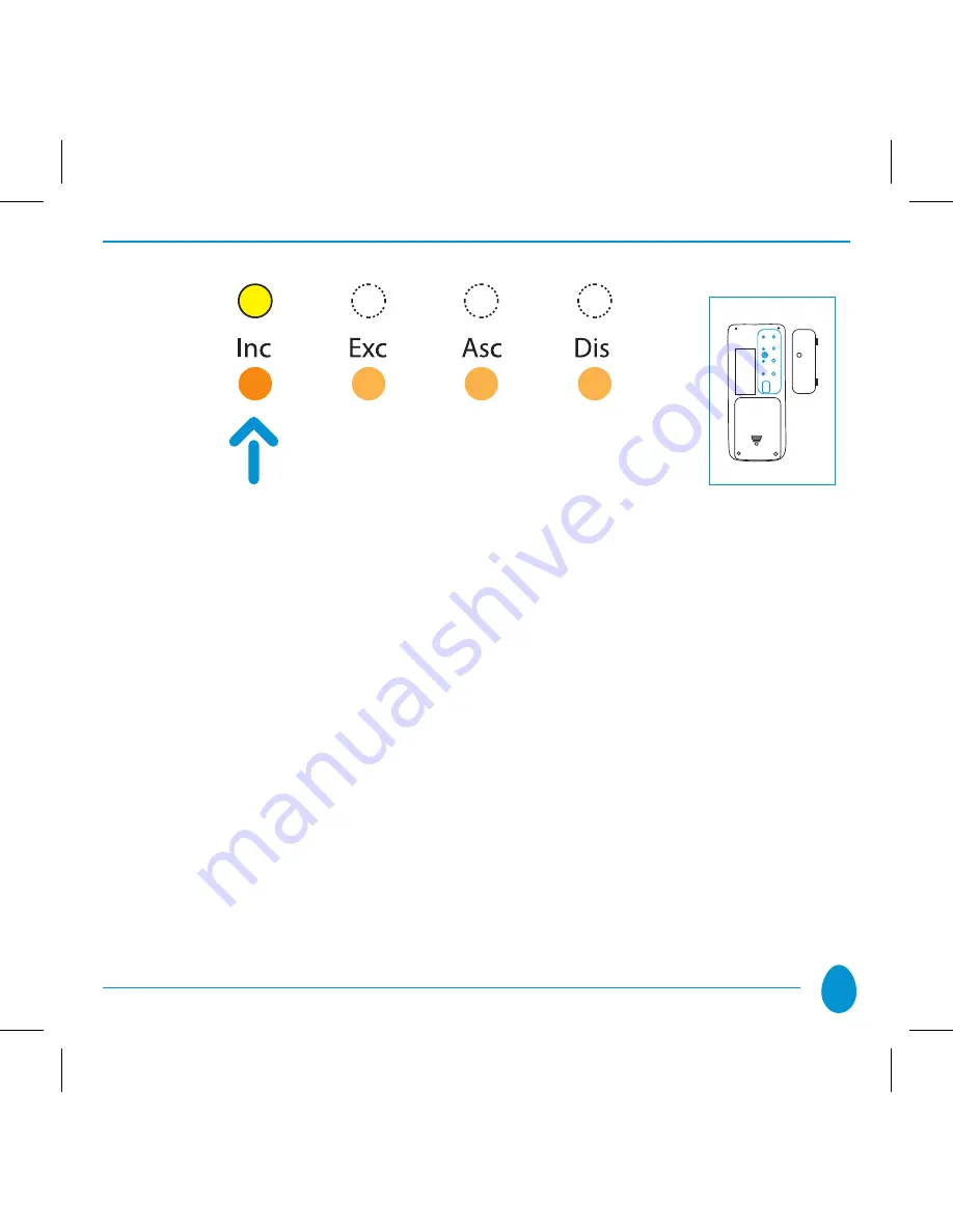
When all the devices have been included, again press the 

• 

“Inc”

 key on the HOME 

MASTER remote handset until the LED switches off. At this point, the illuminated 
ring on each of the Vitrum switches will no longer turn RED when passing from 
one status to another.

NOTE:

 It is not possible to include a device to the network if it has already been 

included in a different network.

Summary of Contents for Home Master

Page 1: ...H O M E C O N T R O L EN INSTRUCTIONS FOR USE Home Master Remote Handset ...

Page 2: ...Contents 1 General view 3 2 Programming Functions 7 3 Warranty 20 4 Compliance 21 5 Maintenance 22 6 Compatibility 22 ...

Page 3: ... a portable control unit that can be used to control every function of a Z Wave system initial creation of the network association of peripheral devices creation of scenarios ecc The front and rear panels of the handset are shown below 1 A B C D 2 3 4 ...

Page 4: ... OFF Long pressure on UP DIMMER UP Long pressure on DOWN DIMMER DOWN LEDS 1 flash RED Peripheral device not included in network 3 flashes GREEN The peripheral units have received the command correctly 3 flashes RED One or more of the peripheral units has not received the command correctly 5 flashes YELLOW Batteries exhausted Keys and LEDs on front panel 1 A B C D 2 3 4 ...

Page 5: ...mal operation to send the control signals on off dimmer up down etc When a command is sent to a peripheral device or to a group of devices the indicator LED flashes GREEN briefly if the signal is received correctly If this is not the case the LED flashes RED to indicate an error ...

Page 6: ...ent houses the programming keys which are used to control the various installation and maintenance operations required for the network inclusion association of peripheral devices creation of scenarios complete reset of the remote handset etc Each key is associated with a LED whose colour indicates the status of the operation being entered ...

Page 7: ...unctions are those used to map the network inclusion association of peripheral devices to set up the desired associations or to reset the remote handset to its original factory settings The programming functions are described in detail below ...

Page 8: ... This procedure is useful in a number of situations especially before creating a new network in this case if the remote handset has previously been utilized with other Z Wave networks it is important to perform a total reset before creating a new network This procedure is designed to prevent any possibility of malfunctions Proceed as follows to perform a total reset Press and hold down the Exc but...

Page 9: ... Release the button and then press again for at least 2 seconds The LED will now flash GREEN to indicate that the remote handset is being reset The button can now be released ALL the LEDs will then flash RED 10 times simultaneously to indicate that the reset procedure has been completed ...

Page 10: ...added and it will become a SECONDARY CONTROLLER In this case the remote handset cannot be used to include or remove peripheral devices Proceed as follows to include a peripheral device using the remote handset The peripheral device must be unused i e it must not be part of another network This can be checked immediately by observing the colour of the LEDs when the status changes a brief RED flash ...

Page 11: ...ndicates that it has been included to the network by flashing the LEDs green three times and switching on all the lights connected to the unit When all the devices have been included again press the Inc key on the HOME MASTER remote handset until the LED switches off At this point the illuminated ring on each of the Vitrum switches will no longer turn RED when passing from one status to another NO...

Page 12: ...evice from the network to which it is connected or simply to make a device unused The procedure is almost identical to that used to include peripheral devices On the rear of the remote handset press and hold down the Exc key until the corresponding LED lights YELLOW after ca 2 seconds ...

Page 13: ...for single channel units the central key Hold the button down for at least 8 seconds For products supplied by other manufacturers refer to the instruction booklet supplied with the device If the procedure is completed correctly Vitrum blinks red tree times and the remote handset automatically exits removal mode To exit manually simply press and hold down the Exc button until the LED switches off ...

Page 14: ...ripheral device or group of devices to the remote handset 2 4 1 Associating peripheral devices with each other In this case the remote handset can be used to create associations connections between the various peripheral devices connected to the network so that one peripheral device can control one or more of these The procedure is extremely simple ...

Page 15: ...edure for all the buttons on peripheral devices to be controlled At this point it is necessary to set up the unit that will be used to control the peripheral device s selected as above To do so press the Asc button the relative LED will light RED Place the remote handset at a distance of not more than 2 metres from the peripheral device which is to control the other devices Press the desired butto...

Page 16: ...ral devices This operating mode is used to remove associations between the peripheral devices connected to the network The procedure is identical to that used for associations except that it is necessary to press the Dis key rather than the Asc key ...

Page 17: ...s also possible to create scenarios which can be memorized in the available slots buttons 1 2 3 4 A B C D You have to use buttons 1 to 4 for creating scenarios before following the procedure you have to set all the light of the scene in the desired way Instead buttons A B C D have function of switching on of or Dimmering lights Proceed as follows Press and hold down the Asc key until the correspon...

Page 18: ...s procedure for all the peripheral devices to be associated with the selected group or scenario When the procedure has been completed or simply to exit the association procedure press the Asc button until the corresponding LED switches off Each time you wish to control the peripheral devices associated with a group or with a scenario it will now be sufficient to press the button relative to that g...

Page 19: ...y it is possible to remove associations from the remote handset or to modify the individual groups or scenarios The procedure is identical to that described above for association of the devices with the exception that the Dis button should be pressed rather than the Asc button ...

Page 20: ...excluding batteries found to be defective as laid down by current legislation This warranty shall become invalid in the case of improper use of or tampering with the remote handset Think Simple shall accept no liability for any damage or injuries that might be caused by a defective remote handset ...

Page 21: ...ications Equipment R TTE 1999 5 EC The manufacturer assumes no responsibility for any use not indicated in this manual Think Simple reserves the right to modify its products at any time and without notice in order to better their quality and functionality Therefore all the information given in this datasheet is to be considered subject to possible modifications ...

Page 22: ...the end of its service life the product should be disposed of correctly at an authorized recycling centre separating the battery and the packaging 6 Compatibility This product is tested and certified Z Wave compliant and has been specifically designed for operation with certified Z Wave products supplied by other manufacturers ...

Page 23: ...23 To discover further functions and products by VITRUM please visit our site www vitrum com ...

Page 24: ... S I M P L E by Think Simple SpA Head Office viale Lino Zanussi 3 Tel 39 0434 516 216 33170 Pordenone Fax 39 0434 516 230 Sales Office corso Garibaldi 86 Tel 39 02 655 600 29 20121 Milano Fax 39 02 454 982 95 www thinksimple it info thinksimple it ...

Reviews: