


95x Series Operating Manual - May 17, 2022
Page
59
of
155
o
The maximum value which can be set is as specified in the Peak Shutdown Current portion of
Surge Current Limiting and Shutdown.
•
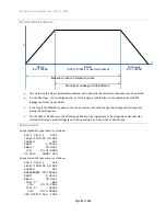
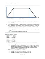
RAMP
. Allows the ramp time period to be programmed either as a time or rate. The
UNIT
key toggles the
selection between these two methods.
o
For loads having >0.03uF capacitance the test ramp time should be >0.1sec. The ramp time may
need to be extended beyond this to ensure the charging current is less than the desired
breakdown detection current. For reference, the charging current (in microamps) = C.(dV/dT)
where C is the capacitance in uF and (dV/dT) is the ramp rate in Volts per second (e.g., 1000V/sec
ramp into a 10uF load is 10000uA =10mA charging current). For optimum results
–
▪
For loads >0.05uF the ramp time should be >0.5sec.
▪
For loads >2uF the ramp time should be >1sec.
▪
For loads >20uF the ramp time should be >2sec.
o
If a load has significant resistance in series with capacitance, then ensure that the charging
current is within the capability of the series resistance to avoid it being damaged. If necessary,
reduce the charging current by using a slower ramp rate.
•
Min Load
. Not available for the DCez type. This is only available if CNFG
–
TEST
–
MIN LOAD is set to YES.
This allows the user to specify a minimum capacitance load which should be encountered during ramp. If
this loading is not encountered during ramp, then the test is failed with a <MIN LOAD status. This
provides an easy to use and very sensitive determination of whether the load is properly connected.
Please note the following
–
o
For settings of below 1nF there must be enough charging current flow during ramp for the set
minimum capacitive load to be successfully detected. For a DUT GROUNDED setting of NO (or
option HSS or HSS-2 not fitted), then the ramp rate should be >1000V/sec for a 1pF setting
reducing to >1V/sec (and lower) for a 1nF (and higher) setting. For a DUT GROUNDED setting of
YES, a setting below 1nF is not recommended.
o
For settings of over 1nF then the actual load capacitance is estimated during ramp and compared
to the Min Load setting (this has no minimum ramp time requirement). This is not an accurate
DUT capacitance measurement, the accuracy is typically 10%.
o
If there is sufficient resistive load, then this is automatically detected and there will be no <MIN
LOAD failure.
o
If the expected capacitive load is known, then a setting of half the expected capacitance is
recommended.
•
DWELL
. Allows the dwell time period to be programmed to the desired time, or it may be set to be user
terminated by pressing the
LIMIT
key while this setting is selected.
•
Delay
. Not available for the DCez type. Allows the user to program a delay within the dwell period before
the leakage range check is to be performed.
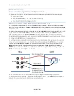
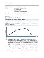
o
The 95x series use a “strong voltage source” method for the DCez, DCW and DCIR types. This
enables the use of much shorter test times when performing testing into capacitive loads since it
is
being both charged and tested from a low impedance source, unlike the “classical” approach of
using a high source impedance to reduce the effects of voltage source noise but needing very
long test times into capacitive loads. For the 95x, there is a short stabilization period required
after the end of ramp when making very low leakage current tests (e.g.,
10’s of nA) with


