95x Series Operating Manual - May 17, 2022
Page
105
of
155
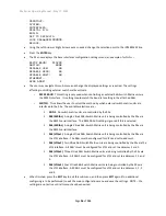
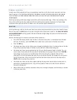
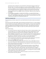
BUILD…
SET TO DEFAULTS…
LOCK PASSWORD:000000
RELOCK…
•
Using the Left Arrow or Right Arrow keys as needed, change the selection point to the DIGITAL I/O line.
•
Press the
ENTER
key.
•
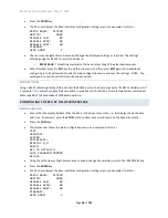
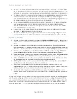
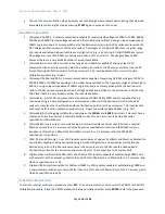
The display now shows the Digital I/O configuration menu. An example of the Digital I/O configuration
menu is as follows
–
START: IGNORE
ABORT: IGNORE
INTERLOCK: IGNORE
PRINT: IGNORE
SEQUENCE: IGNORE
PASS: ACTIVE LO
FAIL: ACTIVE LO
TESTING: ACTIVE HI
DWELL: ACTIVE HI
HV: ACTIVE HI
•
The user may navigate this sub-menu and change the displayed settings as required.
o
START
,
ABORT
,
INTERLOCK
,
and
SEQUENCE
. These allow the user to select whether the
respective digital input is to be ignored, active low or active high.
▪
If either the INTERLOCK signal is enabled and set for active low, or the ABORT signal is
enabled and set for active high, then the 95x will be prevented from running any test
sequence if the DIO signals are removed (e.g., the cable is unplugged). If this is not
intended, then these signals should be used with the opposite polarity (i.e., active high
for INTERLOCK and active low for ABORT).
▪
CAUTION
–
changing the active level of the START signal may cause the 95x to detect a
change in the START signal from the inactive to the active state (e.g., if the signal is high
and the configuration is changed from active low to active high). This may cause a
previously selected sequence to be run and high voltages to become present on the 95x
terminals. The user should ensure that no sequence is selected and that the START
signal will end up being in the inactive state when changing the polarity of the START
signal.
o
PASS
,
FAIL
,
TESTING
,
DWELL
and
HV
. These allow the user to select whether the respective
digital output is to be active low or active high.
•
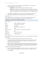
When finished, press the
EXIT
key to exit this sub-menu, and then press
EXIT
again (if no additional
configuring is to be performed) to exit the main configuration menu and save the settings. The settings
are not used until they are saved.
SIGNAL LEVELS
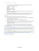
Each input signal has the following characteristics
–
•
Each is referenced to the COMMON signal, which is internally connected to the 95x chassis ground.
•
The maximum input level guaranteed to be recognized as a low level is +1V, the minimum guaranteed to
be recognized as a high level is +2.3V.

