background image

User Guide 

VTouch-Plus Configuration Tool  

VITREA Smart Home Technologies | T: +972.3.5474746 | F: +972.3.5474738 | vitrea-sh.com | 

[email protected]


Page 

27

 of 

27


LIMITED WARRANTY 

Vitrea Smart Home Technologies warrants its products for a period of 18 months from the date of 
purchase from Vitrea or an authorized Vitrea distributor. This warranty may be enforced by the 
original purchaser and subsequent owners during the warranty period, so long as the original dated 
sales receipt or other proof of warranty coverage is presented when warranty service is required. 
Except as specified below, this warranty covers all defects in material and workmanship in this 
product. The following are not covered by the warranty: 

Damage resulting from: 


Accident, misuse, abuse, or neglect. 


Failure to follow instructions contained in this guide. 


Repair or attempted repair by anyone other than Vitrea. 


Failure to perform recommended periodic maintenance. 


Causes other than product defects, including lack of skill, competence or experience of user. 


Shipment of this product (claims must be made to the carrier). 


Being altered or which the serial number has been defaced, modified, or removed. 

Vitrea is not liable for any damages caused by its products or for the failure of its products to 
perform, including any lost profits, lost savings, incidental damages, or consequential damages. 

Vitrea is not liable for damages based upon inconvenience, loss of use of the product, loss of time, 
interrupted operation, commercial loss, any claim made by a third party or made by you for a third 
party. 

Vitrea's liability for any defective product is limited to repair or replacement of the product, at our 
option. 

If your VTouch Plus device needs service, please contact Vitrea by telephone, fax, or email for return 
information. Please do not return products to Vitrea without return authorization. 


Summary of Contents for VTouch-Plus

Page 1: ...S wi t c h t o E l e g a n c e VTouch Plus Keypads Installation Configuration Manual...

Page 2: ...CONFIGURATION SOFTWARE 13 Overview 13 System Requirements 13 Installing the Configuration Tool 13 Connecting the Configuration Tool Software to the VBOX Plus Gateway 14 Configuring the System 14 Rese...

Page 3: ...s Panels 7 Figure 5 Installation of Horizontal and Vertical Glass Panels One Above the Other 7 Figure 6 4 Wire Bus Connectivity 9 Figure 7 VP Gateway Front Panel 10 Figure 8 VP Gateway Back Panel 10 F...

Page 4: ...ress Release Press Release Mode messages when a button is pressed Receive commands to set each button as Satellite or Press Release Mode Receive commands to set the Short and Double press timings Rece...

Page 5: ...EYPADS Horizontal or Vertical Keypad Installation The VTouch Plus keypad can be installed horizontally or vertically The keypad should be positioned in the wall mounting box as shown in the figure bel...

Page 6: ...sh with the wall with a 1 mm line between the wall and the glass Caution The adaptor is made from strong quality Gypsum material Handle it carefully to prevent chips to its corners and sides Read the...

Page 7: ...commended distances between the centers of the wall mounting boxes when installing adjacent VTouch keypads side by side or one above the other The recommended distances depend on the dimensions of the...

Page 8: ...al 2 12 Horizontal Horizontal 2 14 Recommended Distance for Keypads One above the Other Keypad A Keypad B Recommended distance between glass panels cm Vertical distance between centers of the mounting...

Page 9: ...Plus keypads via a 4 wire bus two wires for RS 485 data communication and two for 24 VDC power supply The communication protocol between the VP gateway and the third party Smart Home Processor Contro...

Page 10: ...F 972 3 5474738 vitrea sh com support vitrea sh com Page 10 of 27 Description of the VTouch Plus VP Gateway The VP Gateway manages the communication between the VTouch Plus keypads and the Host The VP...

Page 11: ...ay and Pin 5 is GND Pin 2 connects to the RX of the Host Pin 3 connects to the TX of the Host Pin 5 connects to the GND of the Host The communication parameters are 9600 N 1 Note When the VP Gateway i...

Page 12: ...are internally connected and so are the two connections of VP Gateway d Connect the power supply 2 Connecting the Configuration Tool Software to the VP Gateway a Connect a PC to the USB port of the VP...

Page 13: ...3 10 VBOX Plus Configuration Tool zip and then unzip it to the required local directory taking careful note of the directory s location Create a shortcut on your PC desktop to the VBOX Plus Configurat...

Page 14: ...a few seconds the program connects to the VBOX Plus Gateway and displays a list of existing keypads Note If the USB cable or power to the VBOX Plus Gateway is disconnected during operation reconnect...

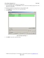
Page 15: ...apter for information Figure 10 System Configuration Page 3 On the System Configuration page click Start Registration 4 On all keypads which are ready to be registered in the system all the orange LED...

Page 16: ...it to the system with the selected ID number Replacing a VBOX Plus Gateway If an existing VBOX Plus gateway needs to be replaced the Auto Setup function should be used Auto Setup enables you to replac...

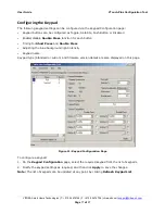
Page 17: ...sable Double Press function for each button Timing for Short Press and Double Press Adjusting the blue background light intensity Keypad name Keypad type Standard or Lutron and firmware version detail...

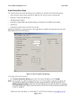
Page 18: ...ort IP address of remote host for TCP Client mode Additional information is also provided on this page about the VBOX Plus Gateway including NIC MAC Address FW version and type Figure 12 Host Connecti...

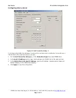
Page 19: ...eway to work with an external Host via Ethernet connection as a TCP IP Client The Host functions as a server 1 On the Host Connection Setup age in the Connection Type field select TCP Client 2 In the...

Page 20: ...Setup 2 To configure the VBOX Plus Gateway to work with an external host via Ethernet connection as a TCP IP Server The host functions as a client 1 On the Host Connection Setup age in the Connection...

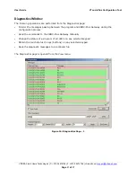
Page 21: ...ostics page Monitor the messages passing between the program and VBOX Plus Gateway during the configuration process Send the commands to the VBOX Plus Gateway manually Change the status of a single or...

Page 22: ...s window content to a computer file On the Diagnostics page click Save to file The file is saved with a date time stamp name in the program s working folder To obtain the touch status of keys buttons...

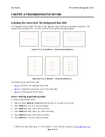
Page 23: ...options Figure 17 3 6 8 Buttons Horizontal Installation Figure 18 3 6 8 Buttons Vertical Installation Programming involves three steps Step 1 Entrance into programming mode Step 2 Programming intensit...

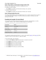
Page 24: ...in memory even when electricity is turned off Resetting the Keypad to Factory Default The keypad is reset to factory default by programming the keys as described below or via the configuration softwa...

Page 25: ...Port One type B Mounting DIN Dimensions 10 W x 9 H x 4 D cm VTouch Plus Keypad Specifications Specification Description Power Supply 12 24 VDC 10mA RS 485 Connection Bi directional Fits into Wall Moun...

Page 26: ...s no guarantee that interference will not occur in a particular installation If this equipment does cause harmful interference to radio or television reception which can be determined by turning the e...

Page 27: ...epair or attempted repair by anyone other than Vitrea Failure to perform recommended periodic maintenance Causes other than product defects including lack of skill competence or experience of user Shi...

Reviews: