3
Recording
5
Network
Setting
4
Search
•
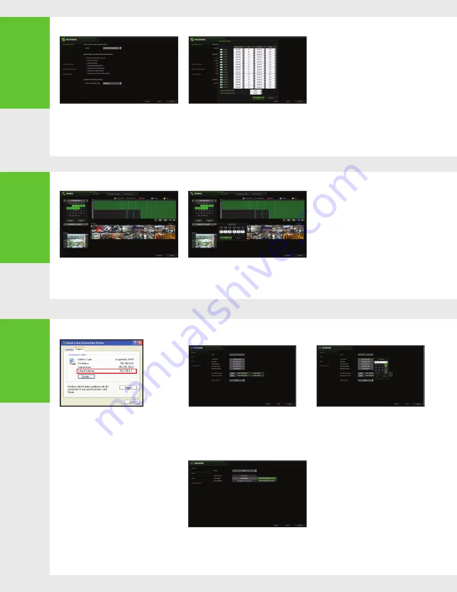
AUTOMATIC RECORDING SETTING
1.
Press [MENU] on the remote control,
and use the direction buttons to select
<RECORD SETUP> and press [ENTER].
Alternatively, you can select <MENU> - <RECORD
SETUP> from the status bar.
2.
Set <RECORD SETUP MODE> to <AUTO
CONFIGURATION>.
3.
Select "Automatic Record Configuration Mode".
• ALWAYS HIGH VIDEO QUALITY :
Recording will proceed in the best quality
regardless of the event at all times.
As this option will always make recording in the
best quality, the recording period is the shortest
compared to the other record modes.
• MOTION RECORD : Recording will proceed only if a
motion is detected.
•
TIME SEARCH
1.
From the <SEARCH> menu, select <TIME SEARCH>.
2.
Specify the search date and time from the calendar in
the left corner of the screen.
3.
You can identify the type of the recording data by the color
in the bar.
• Yellow Green (PRE RECORDING) : The pre-recording
is performed on the recording data after you set
the <PRE RECORDING TIME> from <OPERATION
MODE>.
• Green (Continuous) : The continuous recording is
performed on the recording data.
• Red (Alarm) : The alarm event recording is
performed on the recording data.
• Blue (Motion) : The motion event recording is
performed on the recording data.
• Yellow (Panic) : The panic manual recording is
performed on the recording data.
4.
Click to move to a desired start time in the time
bar, or use the buttons at the bottom of the
status bar to make search.
5.
Select an item to play and click <PLAY>. Click to
move to a desired time, or simply double-click a desired
time in the time bar to play the video data on that time.
•
For details on thumbnail search and event
search, refer to the user manual.
•
NETWORK CONNECTION SETTING
TO CONFIGURE THE NETWORK SETTINGS
1.
Connect the DVR to the router.
2.
Connect the [WAN/UPLINK)] port of the router directly to
the fixed IP LAN cable, or connect it to the ADSL modem.
5.
W h e n t h e n e t w o r k c o n f i g u r a t i o n i s
c o m p l e t e , p r o c e e d wi t h t h e D D N S s e t t in g s .
From the main menu of the DVR, move to <SYSTEM
SETUP> - <NETWORK> - <DDNS>.
6.
R e n a m e t h e D V R . ( T h e d e f a u l t n a m e o f
t h e D V R i s t h e M A C a d d r e s s o f t h e D V R . )
Enter a desired DVR name (combination of characters
and numbers).
1.
From the main menu of the DVR, move to <SYSTEM
SETUP> - <NETWORK> - <IP SETUP>.
2.
Use DHCP to get an IP address from the router, or
manually enter an IP address that falls within the
private IP range provided by the router.
•
IP ADDRESS : 192.168.0.123 (enter the network
IP address.)
• GATEWAY : 192 .168 .0.1 (enter the gateway
address.)
• SUBNET MASK : 255.255.255.0 (type the subnet
mask.)
• 1ST, 2ND DNS SERVER : 168.126.63.1 (enter the
address of a DNS server.)
7.
When done, click <DDNS REGISTRATION TEST>
and <DDNS CONNECTION TEST> in this order.
If you receive a success message. Check the DVR
address and click <APPLY> at the bottom.
8.
Check the DVR address and the Web service port
in the network settings to make sure that any
Internet-connected PC can access the DVR.
9.
If you type "mydvr" for the DVR name from the
DDN item, the address of the Web viewer is
"http://mydvr.dvrlink.net: 8080".
• ALARM RECORD : Recording will proceed only
if an alarm event occurs.
• MOTION/ALARM RECORD : Recording will
proceed only if a motion is detected or an alarm
event occurs.
• INTENSIVE MOTION RECORD : Recording will
be performed in a low quality. However, the
quality will switch to high if motion event is
detected.
• INTENSIVE ALARM RECORD : Recording will
be performed in a low quality. However, the
quality will switch to high if an alarm event
occurs.
• INTENSIVE MOTION/ALARM RECORD :
Recording will be performed in a low quality.
However, the quality will switch to high if an
alarm event occurs or motion is detected.
4.
Click <APPLY>.
3.
When done, configure the port forwarding for the RTSP
and Web Service ports by clicking Port Forwarding.
4.
Click <PORT FORWARDING> for each. You will see
the confirmation message. Click <APPLY> and exit the
menu.
5.
The network settings of the DVR are complete.
N o t e : S ome rou ter mo de ls m ay not supp or t U PN P.
If you see a failure message after clicking <PORT FORWARDING>,
refer to the user manual of the router and configure the port
forwarding settings manually.


