14
14
2). Method of minimum
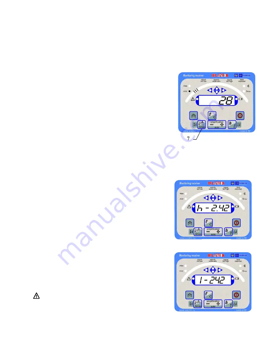
Depress the button pos.7 figure 2.18 to switch to the search
mode by method of minimum. Three segments shall appear on
the screen, their position indicates at what distance and side
there is a buried utilities axis (on figure 2.18 the buried utility is
located to the left). The digital value corresponds to the signal
from the vertical antenna and shall be of minimum value above
the axis. The same button is used to return to the method of
maximum. This method gives higher accuracy of buried utility
detection, that being ±0.15m at a depth
of up to 1…1,5m and
±0.25 m at a depth of up to 10m.
Remark
–
the distortion effect can be encountered when there are space-occupying metal objects,
reinforced-concrete structures, cables or pipelines located near the monitored buried utility.
3). Measurement of depth and current
Place the receiver over the route axis as accurate as possible,
keep it strictly upright (The receiver handle must be directed
along the route axis).
To specify the direction it is possible to slightly rotate the
receiver in the mode of maximum around its vertical axis
reading the signal level on the digital indicator. The maximum
of the readings correspond to the right position. Depress the
button pos.10. The measured depth in meters is depicted on
the screen figure 2.19. The receiver must not move during
measurement.
When the button pos.10 is depressed for the second time the
measured current in milliamps shall be displayed on the
screen in the form of: (242 mA) figure 2. 20. The reading shall
stay on the screen while the button is kept depressed.
If there is an attempt to measure the depth at a frequency at
which this function is not supported («50/60»), the symbol
is illuminated, and the measurement is not conducted.
The receiver cannot calculate the depth accurately enough if
it exceeds 10 m, in this case the value 10,0m blinks on the
screen.
Fig.2.18
Fig.2.19
Fig.2.20


