H E A T I N T E R F A C E U N I T
C O M M I S S I O N I N G
Page 22
H E A T I N T E R F A C E U N I T
C O M M I S S I O N I N G
Page 23
CAUTION
The actuators on the valves must not be
dismantled during operation. This could result in
them being destroyed. Dismantling should only
be carried out when the HIU is isolated from all
systems (mechanical and electrical) and when
the system has cooled down.
Remove end caps and fit flexible hose between
both valves
The secondary HTG circuit pressure should be
typically between 1.0 and 1.5bar, the secondary
HTG system pressure may be read from the
pressure gauge at the front of the HIU
Open the secondary HTG valve first and then
open the MCW valve until the desired pressure
has been achieved
Vent system radiators of all air, top up pressure
after each radiator has been vented
When the system has been fully vented, and
the desired pressure has been achieved, turn
off both valves identified in Fig 15
Remove hose and replace end caps tightly
(always disconnect the filling hose following
use)
Check HIU for leaking joints on the secondary
HTG connections, tighten connections as
required. Do not overtighten the fibre washers
as this will result in damage. Should a fibre
washer become damaged, replace the washer
immediately ensuring to isolate the HIU
mechanically and electrically first
Connect the power cable to the pump (Fig 16).
This cable is removed on purpose to avoid the
pump operating with no water in the system.
To access the pump, move the HIU controller
out of the way
Fig. 16
Once all radiators have been vented, system is at
desired pressure and no leaks are evident, move
to the next step identified in 8.2.3
8.2.3 Filling the Primary System
Only fill the primary system when both
secondary side circuits have been filled as
identified in 8.2.1 and 8.2.2
Open the primary system isolation valves at the
top of the HIU. Always open the flow valve first
to prevent debris entering the HIU
Check HIU for leaking joints on the primary
connections, tighten connections as required.
Do not overtighten the fibre washers as this will
result in damage. Should a fibre washer become
damaged, replace the washer immediately
ensuring to isolate the HIU mechanically and
electrically first
8.3 Finalising the HIU Installation
All joints within the HIU and the final connections
to the HIU are water tight
All DHW outlets have been flushed through to
remove air and debris
All radiators have been vented
Confirm safety relief valve (SRV) has been
connected to drain. Test SRV in line with
manufacturer’s instructions to ensure valve is
operating correctly
WARNING
The safety relief valve is a factory set unit, do
not tamper with the valve. Should the valve not
function when tested or pass water, the valve must
be replaced.
Check all electrical connections are in good
condition and are connected correctly
Confirm all wiring has been completed (power
supply, room stat & programmer) in accordance
with wiring regulations and the HIU has a safe
means of isolating the power supply
8.4 Final Commissioning
Complete correct commissioning form; address,
date, commissioning engineer, HIU details, heat
meter details, confirm any flushing bypass is
closed on the primary connections
Check primary flow temperature is within 5°C of
design set point via the heat meter. If not, wait to
allow hot water to reach HIU
8.4.1 DHW and Keep Warm Control Valve
Adjustment
DHW and keep warm control is provided by Danfoss
AB-QM PICVs. During the commissioning process
the flow rate will need to be checked and adjusted.
See Fig 17 opposite which identifies the location of
(A) DHW PICV and (B) Keep warm PICV.
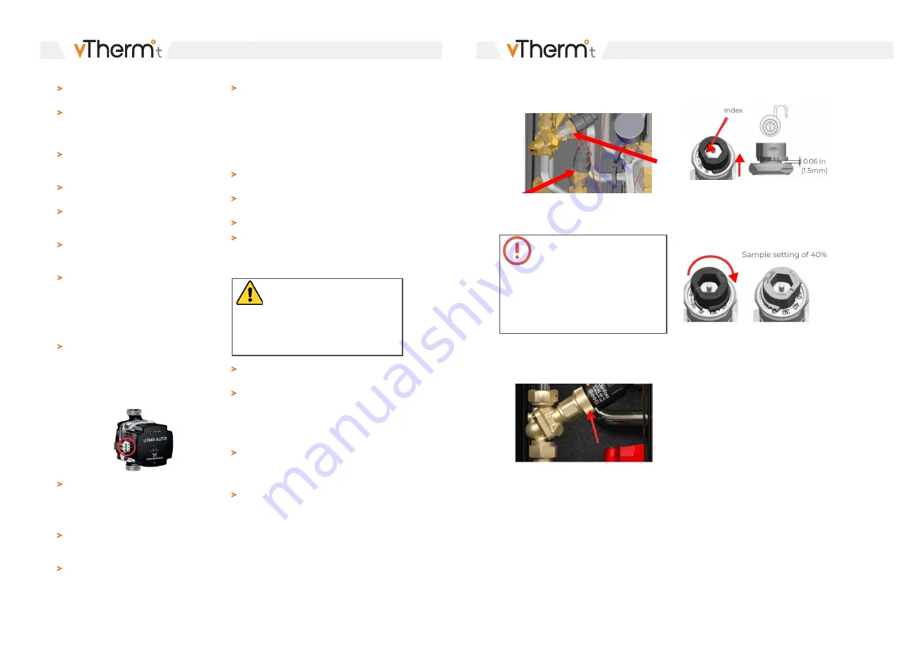
Fig. 17
Fig. 18
A
B
Before undertaking any of the steps below, close
primary system isolation valves at the top of the
HIU and confirm electrical connection is isolated.
Lift the grey adjustment pointer above the setting
grooves (Fig 19). Located on the adjustment
pointer is a red line which is the index for the
adjustment.
Remove thermostatic actuator by loosening the
brass collar (Fig 18).
Fig. 19
Rotate the pointer to the required flow percentage.
Clockwise to decrease the setting percentage,
counter-clockwise to increase the setting
percentage (Fig 20).
Fig. 20


