background image

22

3

/

8

"

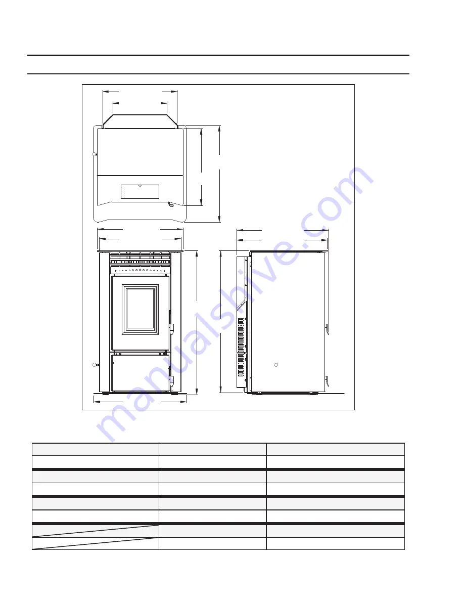
(568mm)

28

1

/

4

"

(716mm)

26

3

/

8

" (671mm)

25" (637mm)

41

7

/

8

"

(1063mm)

15

7

/

8

" (403mm)

21

3

/

4

" (553mm)

26

3

/

4

" (680mm)

41

1

/

4

"

(1048mm)

23

3

/

4

" (605mm)

27" (687mm)

Installation

D

IMENSIONS

 & S

PECIFICATIONS

:

Figure 2: Dimensions of VF170. 

6

Table 1: VF170 Specifications.

Testing Standard

Frequency

Voltage

ASTM 1509-04

60 Hz

110 - 120 V

Fuel type

Current

Max Power

wood pellets - 6mm (1⁄4”) dia.

 3.6 Amps

 432 Watts

Description


Hopper Capacity

Consumption on Low

Residential Wood Pellet Heater

up to 130 lb (59 Kg)

1.7 lb/hr (0.77 Kg/hr)*

Weight (with full hopper)

Consumption on High

 455 lb (206 Kg)

7.6 - 8.3 lb/hr (3.45-3.76 Kg/hr)*

*Note: Consumption will vary with the type of fuel used.

Summary of Contents for VF 170

Page 1: ...ESE INSTRUCTIONS FOR FUTURE REFERENCE TECHNICAL MANUAL 50 1864 PLEASE READ THIS ENTIRE MANUAL BEFORE INSTALLATION AND USE OF THIS PELLET BURNING ROOM HEATER FAILURE TO FOLLOW THESE INSTRUCTIONS COULD RESULT IN PROPERTY DAMAGE BODILY INJURY OR EVEN DEATH Contact your building or fire officials about restrictions and installation inspection requirements in your area ...

Page 2: ...r Intake Locations 9 Mobile Home Installation 10 Corner Through Wall Installation 10 Horizontal Exhaust Through Wall Installation 11 RECOMMENDED Through Wall With Vertical Rise and Horizontal Termination Installation 13 Through Concrete Wall With Vertical Rise Installations 13 Outside Vertical Installations 14 Inside Vertical Installations 15 Hearth Mount Installation 16 Slider Damper Set Up 17 Tr...

Page 3: ...stove again until you are certain the chimney and its lining have not been damaged OPERATION The door and ash drawer must be kept closed when the unit is in operation to prevent fume spillage and for proper and safe operation of the pellet stove Also ensure all gaskets on the door are checked and replaced when necessary Unit hot while in operation Keep children clothing and furniture away Contact ...

Page 4: ...s appliance must be installed on a floor with an adequate load bearing capacity if existing construction doesn t meet load capacity suitable measures e g load distributing plate must be taken to achieve it DO NOT INSTALL A FLUE DAMPER IN THE EXHAUST VENTING SYSTEM OF THIS UNIT DO NOT CONNECT THIS UNIT TO A CHIMNEY FLUE SERVING ANOTHER APPLIANCE FRESH AIR This unit uses large quantities of air for ...

Page 5: ...id surface wood metal or approved hearth pad must be installed between the unit and the carpet 6 This unit uses large quantities of air for combustion outside Fresh Air connection is strongly recommended Fresh Air must be connected to all units installed in Mobile and Air Tight Homes R2000 or where required by local codes 7 Do not obtain combustion air from an attic garage or any unventilated spac...

Page 6: ...0 Specifications Testing Standard Frequency Voltage ASTM 1509 04 60 Hz 110 120 V Fuel type Current Max Power wood pellets 6mm 1 4 dia 3 6 Amps 432 Watts Description Hopper Capacity Consumption on Low Residential Wood Pellet Heater up to 130 lb 59 Kg 1 7 lb hr 0 77 Kg hr Weight with full hopper Consumption on High 455 lb 206 Kg 7 6 8 3 lb hr 3 45 3 76 Kg hr Note Consumption will vary with the type ...

Page 7: ... using a 2 x 18 gauge wire from the unit to the thermostat If the heat in the room becomes to great the high limit switch may turn the stove off and the switch will have to be manually reset To reset the high limit switch remove the right cabinet side The switch is found on the air jacket Remove jumper wire and install thermostat wires here Figure 5 Thermostat wire placement HEARTH SHIELD INSTALLA...

Page 8: ...ermination locations Table 2 Use in conjunction with Figure 6 for allowable exterior vent termination locations Letter Minimum Clearance Description A 24 in 61 cm Above grass top of plants wood or any other combustible materials B 48 in 122 cm Beside below any door or window that may be opened 18 46 cm if outside fresh air installed C 12 in 30 cm Above any door or window that may be opened 9 23 cm...

Page 9: ...take must be below and a minimum of 12 30cm away from the unit exhaust outlet Outside fresh air is mandatory when installing this unit in airtight homes and mobile homes When connecting to an outside fresh air source do not use plastic or combustible pipe A 3 minimum 76 mm ID inside diameter steel aluminum or copper pipe or ducting should be used It is recommended when you are installing a fresh a...

Page 10: ...the floor using the four 4 holes in the pedestal Ensure the unit is electrically grounded to the chassis of your home permanently Do not install in a room people sleep in Outside fresh air is mandatory Secure outside air connections directly to fresh air intake pipe and secure with three 3 screws evenly spaced CAUTION THE STRUCTURAL INTEGRITY OF THE MANUFACTURED HOME FLOOR WALL AND CEILING ROOF MU...

Page 11: ...m away from the wall If the stove is to be set on a hearth pad set the unit on it 2 Locate the center of the exhaust pipe on the stove Extend that line to the wall Once you have located the center point on the wall refer to pellet vent manufacturer installation instructions for correct hole size and clearance to combustibles 3 Install the wall thimble as per the instructions written on the thimble...

Page 12: ...rough wall installations have 3 to 5 feet 91 to 152 cm of vertical pipe in the system to help naturally draft the unit in the event of extreme weather or a power outage Some horizontal through wall installations may require a T and 3 to 5 feet 91 to 152 cm of vertical pipe outside the building to help draft the unit This may be required if a proper burn cannot be maintained after the stove has bee...

Page 13: ...ermination cap Vertical section of vent pipe Horizontal frame for thimble 90o elbow Concrete Wall Clean out tee Installation to use if there is a concrete or retaining wall in line with exhaust vent on pellet stove A 45 down elbow may be used in place of the termination cap or stainless steel termination hood The termination must be 12 inches 30 cm from the outside wall and 12 inches 30 cm above t...

Page 14: ...ean out on the outside of the house 2 Install PL vent upward from the tee Make sure that you install support brackets to keep the vent straight and secure 3 Install ceiling thimble and secure the flashing as you go through the roof 4 Ensure that the rain cap is approximately 24 61 cm above the roof Rain cap Flashing 24 61 cm 4 10cm Tee with cleanout Fresh air intake 3 7 5 cm Clearance Support brac...

Page 15: ... the unit in a manner so when the pellet vent is installed vertically it will be 3 7 6 cm away from a combustible wall 2 Install the tee with clean out 3 Install the pellet vent upward from there When you reach the ceiling make sure that the vent goes through the ceiling fire stop Maintain a 3 7 6 cm distance to combustibles and keep attic insulation away from the vent pipe Maintain an effective v...

Page 16: ...all a sealing plate at the top of the chimney 4 Connect a rain cap and flex adapter to the chimney liner pipe 5 Connect a clean out tee or a 90 elbow to the liner pipe 6 Install tee onto stove Floor Protection Combustible Floor Masonry Fireplace Min 150mm 6 Mantel Minimum 200mm 8 from top of stove Damper Removed or Fastened Open Clean out Fresh air intake should com from chimney If holes already e...

Page 17: ... either end of range in which the unit runs correctly and has a good flame pattern Pull the rod out until the flame becomes a short brisk flame like a blowtorch push the rod in a little and mark it The next mark its the most important and is set with a magnehelic IMPORTANT Taking a reading of vacuum pressure inside the firebox with a magnehelic gauge should be used to set the slider for best combu...

Page 18: ...he Heat Level Indicator If the 3 light is flashing unit may be out of fuel üCheck the Door and Ash Pan door THEY MUST BE CLOSED TIGHT üSee section 8 The pellets will not light üCheck the fuse on the circuit board üIf the unit still does not start contact your local service dealer for service 2 The stove will not operate when hot üCheck the Heat Level Indicator if a fire is not detected or if the f...

Page 19: ...hen hot 3 The Exhaust motor will not function normally and 5 Auger light flashes turn at all for more suggestions üTo reset Circuit Board after a trouble code push the ON OFF button 5 Auger light flashes but auger motor does not turn at all üCheck the Door and Ash Pan door THEY MUST BE CLOSED TIGHT üIf the Auger gear box does not turn but the motor s armature does try to spin then the auger is jam...

Page 20: ...solid then control of the unit is given back to the operator üCheck position of the Thermostat slide switch on the Circuit Board üIf there is no control of the Heat Level button make sure the thermostat is calling for heat üCall your local dealer for service 10 The stove keeps going out If the stove goes out and leaves fresh unburned pellets or cigarette like ashes in the burn pot liner the fire i...

Page 21: ...hite White White White Black White Orange Orange Yellow Yellow Grey Purple Purple Blue Black Black Black Blue Vacuum Switch Combustion Blower Ignitor Exhaust Temperature Sensor 5 Amp Fuse High Limit Temperature Sensor Convection Blower Auger Motor Thermostat Ground Yellow 120V Grounded Plug ...

Page 22: ...8 Auger Brass Bushings Set Of 2 EF4i 065 9 IEC Power Cord Inlet Socket 50 713 10 Circuit Board 5 Amp Fuse 115V Set of 2 50 833 11 5 8 ID Auger Collar with Screw 50 968 12 Slider Damper Set Collar Kit 50 1068 13 Auger With Paddles 50 1161 Burn Pot Scraper Tool 50 1254 14 Leveling Legs 11 2 Set of 4 50 1342 15 Vacuum Switch Low Pressure 50 1390 Auger Tube Cover 50 1410 16 Exhaust Starter Tube Gasket...

Page 23: ...er Assembly 50 1660 36 Burn Pot 50 1661 37 Burn Pot Liner 50 1662 38 Exhaust Starter Tube with Flange Ø3 x 5 50 1663 39 Combustion Blower Motor Mounting Gasket 50 1664 Circuit Board Wiring Harness 50 1666 40 Door 50 1851 41 Trivet 50 1852 42 Top Front with Mount 50 1853 43 Cabinet Side Left 50 1854 44 Cabinet Side Right 50 1855 45 Louver Assembly 50 1856 46 Front Trim Panel 50 1857 47 Ash Pan Door...

Page 24: ...Parts Diagram Components VF 170 Components May 2008 24 ...

Page 25: ...25 Parts Diagram Steel VF 170 Steel Components May 2008 ...

Page 26: ...in restrictions and exclusions apply to this warranty Limited Two 2 Year Warranty Under this warranty Sherwood Industries Ltd covers Ignitor Auger Motor Circuit Board Timers Temp Sensors Blowers Vacuum Switch and Wire Harness against defects in materials and workmanship for part repair or replacement for the first two 2 years and limited labour for the first two 2 years to the original purchaser P...

Page 27: ...lify the Limited Warranty on this stove If unsure as to the extent of this Limited Warranty contact your authorized Vista Flame dealer before installation 10 Sherwood Industries Ltd will not be responsible for inadequate performance caused by environmental conditions 11 The Limited Warranty does not cover installation and operational related problems such as spillage caused by environmental condit...

Page 28: ... covered per our warranty service fee reimbursement schedule Labour rates are set per component and as such total labour costs may not be covered 27 Sherwood Industries Ltd is not liable for freight or labour on any stove replaced in field and is not liable for travel costs for service work In the event of in home repair work the customer will pay any in home travel fees or service charges require...

Page 29: ...____ SERIAL NUMBER ___________________________ DATE OF PURCHASE _____________ dd mm yyyy DATE OF INSTALLATION ___________ dd mm yyyy MAGNEHELIC AT INSTALL ___________________ INSTALLER S SIGNATURE _________________________________________ NAME OF INSTALLER _________________________________________ ADDRESS _________________________________________ _________________________________________ _________...

Reviews: