background image


Document: CL140072 

L2174 Manual Issue 2.0 

Page 16 of 26 

9


M

AIN 

D

ISPLAY


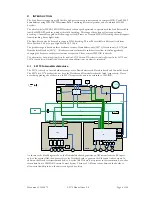
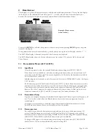
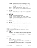
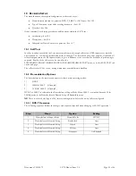
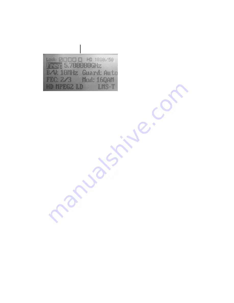
This displays, at a glance, the current frequency selection and modulation parameters. The top line also displays 
the lock status of the individual RF and ASI inputs ( 

9

 = locked ), and the video format detected by the 

decoder. The bottom line displays the currently selected Decoder and Demodulator Modes. 

RF Lock 

Status 1-4

ASI Lock

Decoded 

Video Format

Decoder mode

Demodulator mode


Pressing the 

MENU

 key will take the operator to the main setup menus; pressing 

MENU

 again at any point 

returns to this display. 

If any parameter has not yet been initialised (e.g. shortly after power-up), then it will display as dashes (“---“). 

The L2074 Main display is identical, except the Video Format is not displayed. 

The L2170 Main display shows the Service selection menu (see section 9.2.1), plus the ASI lock status and 
Video Format. 

9.1


Demodulator Menus (L2174, L2074) 

9.1.1


Input Mode 

Allows the operator to select the required Modulation scheme being used (DVB-T, LMS-T). 

When the unit is first switched on, and when switching modulation modes, the unit performs a self 

test routine on the RF front end. This causes a slight delay (15-30s) before the demodulator will lock. 
For more details see section 10.2 

Individual inputs can be turned on and off as required. Note that in 20MHz LMS-T mode, only Inputs 
1 & 2 are active. 

The Receiver supports the Link Remote Triax System (L1273/4), which allows downconverters to be 
sited remotely (up to 1km from the receiver). This can be set to Single or Dual mode; in Single mode, 

2 downconverters are mounted remotely, and the triax system is connected to RF1 and RF2 on the 
Receiver. The other 2 inputs can be connected directly to downconverters. In Dual mode, two triax 

systems are connected, to RF 1/2 and RF3/4 respectively. This feature defaults to Off. 

9.1.2


Demodulator Setup 

Operator can configure Frequency, Bandwidth, Guard Interval and Polarity. Apart from Frequency, all 
have ‘Auto’ modes, which allows the Demodulator to detect the correct configuration from the 

received signal. 

If a frequency is entered that is outside the range of the currently selected downconverter, then an 

‘Invalid Frequency’ alarm will occur, and reception will not be possible, 

9.1.3


Downconverters 

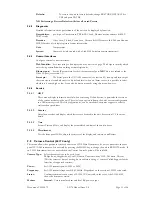
For each RF input, select the downconverter type, and turn on power to the downconverter. All 

current Vislink downconverters are listed, or the Local Oscillator (LO) frequency of any unlisted 
downconverter may be entered by selecting OTHER. To enter the incoming UHF frequency directly, 

select NONE. When NONE is selected, downconverter power is disabled. 

To change all RF inputs to the same downconverter settings at the same time, SET ALL INPUTS 

should be set to ON; to set them individually, turn this setting OFF. 

Example Home screen 

(when locked) 

Summary of Contents for Lynx L2174

Page 1: ...Docu ument CL140 0072 Lynx R PROD Receive DUCT M r L217 MANUA 4 L207 L AL 74 L21 L2174 Manual 70 l Issue 2 0 ...

Page 2: ...mera Control Alarm 12 6 10 Ethernet Control 12 6 11 Ethernet Video over IP 12 7 Controls 12 7 1 Selection keys 12 7 2 Menu scroll keys 13 7 3 Hot Keys 13 7 4 LEDs 13 7 5 USB port 13 8 Operator Menus 13 9 Main Display 16 9 1 Demodulator Menus 16 9 2 Decoder Menus 17 9 3 Stream Management Menu 18 9 4 System Menu 18 9 5 Camera Control 19 9 6 Web Browser Operation 20 10 Receiver Set up 22 10 1 Self Te...

Page 3: ...r V0009 release 2 0 September 2011 Updated for V0014 release including L2170 L2074 2 2 Firmware Version This manual is based upon Firmware version V0013 Please see the website for details of latest firmware revision 2 3 Support For more information or for service support please contact Worldwide Advent SATCOM Link Wireless Cameras UKsupport vislink com 44 0 1442 431410 Americas Advent SATCOM Link ...

Page 4: ...s sectional area to allow disco SERVICE P DOUBLE P dentical ratings nvironmental l ld open the pr ed to be CE co 2174 Manual Is s supply is ach and be appro onnection PERSONNE POLE NEUT s to the origina limits and ensu roduct and any ompliant and T ssue 2 0 hieved through oved to the rele L CAUTIO TRAL FUSIN al parts fitted i ure as much ve y repair or warr Technical files h a detachable m evant n...

Page 5: ...nised standards ETSI EN 301 489 1 EMC standard for radio equipment and services Part 1 Common technical requirements ETSI EN 301 489 28 EMC standard for radio equipment and services Part 2 Specific conditions for wireless digital video links ETSI EN 302 064 Harmonised EN for Wireless Video Links WVL operating in the 1 3 GHz to 50 GHz frequency band EN60950 Safety of Information Technology equipmen...

Page 6: ...fore allow for field upgrades by changing the license to enable extra features as required Please contact VISLINK for details This document has been written primarily for the complete L2174 Receiver Where there are major differences for the L2170 and L2074 variants they will be indicated however some minor differences may not always be documented 4 1 L2174 Internal Architecture The L2174 is based ...

Page 7: ...rt 720 line 1280 640 SD Horizontal Resolution support 576 480 line 720 704 640 540 528 480 360 352 Not supported in Low Delay mode other resolutions will work but artefacts may be observed Chroma Format 420 422 Bit Depth 8bit MPEG2 8 9 10 bit H 264 Maximum Bit Rate 80Mbit MPEG2 Audio Formats supported MPEG 1 Layer 1 20 bit 48kHz MPEG 1 Layer 2 20 bit 48kHz SMPTE 302M 20 bit 2 channel 48hHz 8ms fra...

Page 8: ... adequate airflow Size Height 44mm Width 210mm Depth 375mm including rear panel connectors Small form 1U width 19 rack mount Weight 1 2kg Operating temperature range Ambient 0ºC to 50ºC Power AC input option 90 VAC to 264 VAC 50Hz to 60Hz max current 1A rms DC input option 9 VDC to 36 VDC ve chassis earth max current 10A 70Watts excluding the downconverters requirements 90Watts max allowing for do...

Page 9: ... puts 1 2 are mounted sock Decoder Packe L2 ONNECTION 4 L2074 or 3 4 are non Hz LMS T RF should also be 860MHz meets or excee el 2W CW o 9 1 Demodul output set in short circuit p used in Single ket Complies w et diversity blo 2174 Manual Is NS n operational 1 2 are used e used to confi eds ES 202 239 lator Menu n Unit LNB P protected mode in Dua with ISO IEC ock ASI outpu ssue 2 0 d for connecti i...

Page 10: ...MPTE 259M 270Mb s HDSDI SMPTE 292M 1 485Gbps For configuration please see 9 2 2 For Video formats supported see section 5 6 5 ASI out 75Ω BNC chassis mounted socket Complies with ISO IEC 13818 2 188byte mode ASI output from the Demodulator Diversity or ASI input for decoding by an external decoder or chaining to another L2174 On the L2074 there are 2 separate ASI outputs which can be configured se...

Page 11: ...nd the Ri see 9 2 3 t damage can o power applied n is provided o udio 1 L2 ounted plugs Functio Audio G Live Return o provide eith he Right chann occur to the au d on the audio ou dB mum 66dB RMS 305CLV Functio Left Lin Left Lin GND Right Li Right Li ovide either an ight channel ca occur to the au d on the audio ou 2174 Manual Is on Analogue Gnd er analogue or nel carries the d udio output am utpu...

Page 12: ...n ser assuming t L2174 MIB txt ersion relevant ver IP t connection fo upported parate from the ntry to main op turns to top of r up a level wh t committing to 2174 Manual Is et EEF on ontrol Rx inpu ontrol Tx outp output open d ed for future u a Return Data T a the L1500 tra n extracted fro amera Control only supported t by default is p e 9 4 3 or web ntrol of the uni nt Information the IP address...

Page 13: ...rted e menu structu overview of ea licensed option t Vislink giving 2174 Manual Is select an optio a choice of se pressing ENT hows the param us of the menu tom selecting ou back to the ser directly to t corner pressin ing up a displa up a display sho ee example scre gh the 3 screen NU ont panel betw ntrolled is the peration and il that require im error is listed cates power is whether the fr d fo...

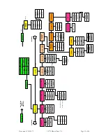
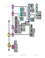
Page 14: ...r Bitrate Sample Rate Layer Auto DECODER CONFIG DECODER STATUS KEY Any Alarms RF Bars MER Bars More Video Format Video Mode Constellation Audio 1 A B Lock status Default Service Audio DIDs DOWNCONVERTERS Input 1 DEMODULATOR continued INPUT MODE Input select Input 1 Input 2 Input 3 Input 4 Frequency Bandwidth Guard Interval Polarity DEMODULATOR SETUP Demod Mode Input 2 Input 3 Input 4 Downconv Othe...

Page 15: ...Document CL140072 L2174 Manual Issue 2 0 Page 15 of 26 ...

Page 16: ...required Note that in 20MHz LMS T mode only Inputs 1 2 are active The Receiver supports the Link Remote Triax System L1273 4 which allows downconverters to be sited remotely up to 1km from the receiver This can be set to Single or Dual mode in Single mode 2 downconverters are mounted remotely and the triax system is connected to RF1 and RF2 on the Receiver The other 2 inputs can be connected direc...

Page 17: ...is of the correct format SD HD and is not scrambled or a valid descrambling key has been entered Once selected this service name will become the preferred or Default service such that on power signal interruption this particular service will be the only one that is decoded on restoration of power signal If the preferred service name appears in a particular multiplex this is the one that will be de...

Page 18: ...e offset required in pixels 9 2 4 2 Descrambling Select Descrambling mode if licensed and enter key s 9 2 4 3 RS232 Data Enable extraction of embedded data from the MPEG stream Displays the detected baud rate and parity Displays dashes if no data detected 9 2 4 4 Identifiers Audio DIDs Selects into which SDI Group the two Audio channels will be embedded PIDs The PIDs detected in the currently sele...

Page 19: ...ation useful when contacting Vislink Service in particular the versions of the various modules in the unit There is also an option to dump the unit s current configuration to a USB memory stick This file configuration txt can be emailed to customer support in order to assist with any problems 9 4 4 2 Licenses Enter licence codes and display which features are licensed in the unit See section 11 1 ...

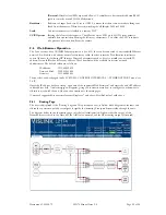
Page 20: ...rnet Ex uting diagram configure the p outing page in ecoder the AS 2174 Manual Is F output and a 1255 Modem u If set to 1152 n correctly wo ked to a remot ter to 1 enabl Setting the left from the came ort on it see 6 crossover cable otocol parame These numbe ws CONTROL e of the suppo ar giving you ontinue to the xplorer 7 and a m This present paths the inco its default con SI Out connec ssue 2 0 l...

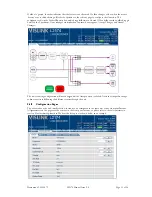
Page 21: ...will not chang different route es face allow the u the same as in n The demodu 2174 Manual Is feature is not rator to the rel which toggles b ade then two n ge until the Ac es through the unit to be con the front pan ulator page is s ssue 2 0 licensed If a b levant page to between On an new boxes app ccept button is unit nfigured in the el menus so p hown below a box changes co configure that nd O...

Page 22: ...ed Results of the self test can be viewed in the SYSTEMÆDIAGNOSTICSÆDEMODULATORÆMOREÆSELF TEST menu or on the SELF TEST tab on the web page The self test takes 15 30s to run during which time demodulation is disabled 10 2 Demodulation Options The demodulator in the receiver can operate in three main operating modes 1 DVB T 2 10MHz LMS T if licensed 3 20 MHZ LMS T if licensed DVB T or LMS T is sele...

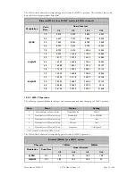
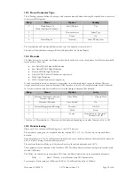
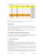
Page 23: ...112 64 QAM 1 2 14 929 16 588 17 564 18 096 2 3 19 906 22 118 23 419 24 128 3 4 22 394 24 882 26 346 27 144 5 6 24 882 27 647 29 273 30 16 7 8 26 126 29 029 30 737 31 668 10 2 2 LMS T Operation The following sequence defines the changes and sequence required when changing to LMS T operation Step Menu Option Setting 1 Demodulator Æ Input Mode Demod Mode LMS T 2 Demodulator Æ Demod Setup Bandwidth 10...

Page 24: ... Transport Stream block if licensed In Auto Service mode the first available service in the transport stream will be decoded Step Menu Option Setting 1 Decoder Æ Decoder Config Æ Decoder Options Video Mode 1 Required Mode 2 Decoder Æ Services Auto Service On 3 Stream Management ÆRouting Diversity On Off 4 Mode Basic 5 Source Demodulator Diversity External ASI IP Only one of Demodulator or Diversit...

Page 25: ... option allows for the use of third party down convertors with the L217x receiver The user must first select Other down convertor type in the DemodÎDownconverter menu then select the required LO frequency and polarity These can be set individually for each of the RF inputs These can then be stored as any one of the Config memories to be re loaded as required 11 LICENSES AND UPGRADES 11 1 Licensing...

Page 26: ... wil de will take app d whilst the up SB stick and cy nuing with sett on the USB st ows systems 2174 Manual Is shown on the mware upgrade Please consult e releases port The requ r first deleting of the memory e unit Also re d apply power ll indicate the proximately 20 pgrade is in p cycle the power ting up the un tick in the file ssue 2 0 licensed featu es providing ne the Vislink we uired file ca...

Reviews: