background image


5 Operating Instructions: 


Hardwire Option: - Connect BLACK wire of 

MAIN HARNESS 

to ground. Connect RED wire of 

MAIN 

HARNESS

 to 12VDC power supply. To verify that the system is receiving power, cup your hands over the 

camera lens, and the LED lights will have a red glow

The green wire is only used if you want the C2 input to 

automatically display when the vehicle is put into reverse.  If this is your preference please attach this wire to 
the appropriate connection on your vehicle.


Ref. Fig.2 


                                                    Ref. Figure > 


Power Button


– press to power on/off monitor and camera system. 


Menu Button


– press simultaneously to adjust 

Picture

System

Volume

Mirror Image

Clock/Trigger 

Delay. 

Menu options will disappear 5 seconds after menu button is pushed. Ref. Fig.3 


Picture

 - use AV button and + / - buttons to adjust brightness, contrast, color, and tint. Picture reset 

can also be selected to reset picture to factory default settings. 


System

 - use AV button and + / - buttons to adjust language, rotation, and system settings. 


Volume

 - use + / - buttons to adjust monitor volume. 


Mirror Image

 - use AV button to select Mirror option and + / - buttons to activate/deactivate mirror 

image. 


Clock

 - use AV button to select camera and + / - buttons to increase/decrease delay time of image 

when the trigger wires are used in the system. 


Mode Button


– used to quickly alter the display for different pre-set brightness and contrast settings.   When 

you plug a second camera into the monitor harness…you can chose CH1 or CH2 for the camera that you 
want displayed on the screen 


Reverse Screen

 - To reverse image on screen press menu button until TCON is displayed. Press the up or 

down button (this is a useful function when you want to mirror or un-mirror the image on the screen).  


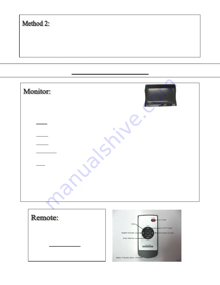
Note: Battery Protective Sleeve must be 
removed prior to use. 
 
 
Reference Monitor Functions in chapter 
4.5 for definitions of Remote Control 
button commands. Ref. Fig.4 


Summary of Contents for VWIC700

Page 1: ...se that is not returned within 30 days of the invoice date is subject to a restocking fee of 15 Contact your Vision Works dealer for return information Merchandise that has been special ordered cannot be returned for credit Non stock items returned for credit will be subject to vendor s return policy Important 1 To prevent short circuit make sure that the system is not plugged in or receiving powe...

Page 2: ...io input dual channel single image display Low Temp Rating 20 C 4 F System PAL NTSC automatically Magnet Yes Voltage 12V 24V Auto Shading Yes Language Multi language OSD Menu Display menu brightness color contrast adjustable Built in Speaker Included Bracket Accessories U type bracket Sunshade Removable Set Up Mirror for individual image can set reserve trigger delay in clock settings 2 0 Parts Id...

Page 3: ... These are the steps required to attach the magnet to the camera 1 Position and align center hole of camera and bracket assembly on top of magnet 2 Install bolt from underside of magnet and secure with flat washer and nut Tighten this connection Tip Although magnet contains 65lb pull force it we recommend mounting your camera on a flat surface and a zip tie be used in addition to fasten the camera...

Page 4: ...r 4 Optional suction cup mounts are also available through your local dealer Connect MONITOR harness to the MAIN HARNESS MONITOR INPUT Ensure arrows are aligned on outer jacket of cable ends Turn silver cable connector nut clockwise to secure connection of the cables IF YOU BEND THE PINS IT VOIDS THE WARRANTY Ref Picture Below Fig 3 Connect VIDEO EXTENSION CABLE harness to C1 input on MAIN HARNESS...

Page 5: ...r is supplied to the GREEN wire on the MAIN HARNESS Note A common application for the C2 video feed is for rear view imaging when in reverse For C2 video feed for a reverse application it is common to connect the GREEN wire to the reverse wire on the vehicle Ref Fig 2 Included in kit is an AV Accessory Cable adaptor that will allow you to play videos from a DVD player or alternate video source It ...

Page 6: ...et can also be selected to reset picture to factory default settings System use AV button and buttons to adjust language rotation and system settings Volume use buttons to adjust monitor volume Mirror Image use AV button to select Mirror option and buttons to activate deactivate mirror image Clock use AV button to select camera and buttons to increase decrease delay time of image when the trigger ...

Reviews: