


TSOP572.., TSOP574..
www.vishay.com
Vishay Semiconductors
Rev. 1.8, 27-Feb-15
3
Document Number: 82434
THIS DOCUMENT IS SUBJECT TO CHANGE WITHOUT NOTICE. THE PRODUCTS DESCRIBED HEREIN AND THIS DOCUMENT
ARE SUBJECT TO SPECIFIC DISCLAIMERS, SET FORTH AT
www.vishay.com/doc?91000
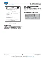
TYPICAL CHARACTERISTICS
(T
amb
= 25 °C, unless otherwise specified)
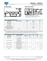
Fig. 1 - Output Active Low
Fig. 2 - Pulse Length and Sensitivity in Dark Ambient
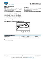
Fig. 3 - Output Function
Fig. 4 - Output Pulse Diagram
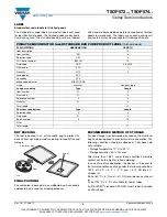
Fig. 5 - Frequency Dependance of Responsivity
Fig. 6 - Sensitivity in Bright Ambient
16110
E
e
T
t
pi
*
t
* t
pi
10/f
0
is recommended for optimal function
V
O
V
OH
V
OL
t
Optical Test Signal
(IR diode TSAL6200, I
F
= 0.4 A, 30 pulses, f = f
0
, t = 10 ms)
Output Signal
t
d
1)
t
po
2)
1)
7/f
0
< t
d
< 15/f
0
2)
t
pi
- 5/f
0
< t
po
< t
pi
+ 6/f
0
1.0
0.2
0.3
0.4
0.5
0.6
0.7
0.8
0.9
0.1
1
10
10
2
10
3
10
4
E
e
- Irradiance (mW/m
2
)
t
po
- Output Pulse Width (ms)
Input Burst Length
Output Pulse Width
λ
= 950 nm,
Optical Test Signal, Fig.1
0
0.1
E
e
t
V
O
V
OH
V
OL
t
600 µs
600 µs
t = 60 ms
t
on
t
off
94 8134
Optical Test Signal
Output Signal
, (see fig. 4)
0
0.1
0.2
0.3
0.4
0.5
0.6
0.7
0.8
0.1
1
10
10
2
10
3
10
4
10
5
E
e
- Irradiance (mW/m
2
)
t
on
, t
off
- Output Pulse Width (ms)
λ
= 950 nm,
Optical Test Signal, Fig. 3
t
off
t
on
0.0
0.2
0.4
0.6
0.8
1.0
1.2
0.7
0.9
1.1
1.3
f/f
0
- Relative Frequency
16925
f = f
0
± 5 %
Δ
f(3 dB) = f
0
/10
E /E - Rel. Responsivity
e min.
e
0
0.5
1.0
1.5
2.0
2.5
3.0
3.5
4.0
0.01
0.1
1
10
100
E
e
- Ambient DC Irradiance (W/m
2
)
E
e min.
- Threshold Irradiance (mW/m
2
)
Correlation with Ambient Light Sources:
10 W/m
2
= 1.4 kLx (Std. illum. A, T = 2855 K)
10 W/m
2
= 8.2 kLx (Daylight, T = 5900 K)
Wavelength of Ambient
Illumination:
λ
= 950 nm
4.5
5.0


