Vishay TSOP57236 Manual Download Page 10

TSOP572.., TSOP574..

www.vishay.com

Vishay Semiconductors


Rev. 1.8, 27-Feb-15

10

Document Number: 82434

THIS DOCUMENT IS SUBJECT TO CHANGE WITHOUT NOTICE. THE PRODUCTS DESCRIBED HEREIN AND THIS DOCUMENT

ARE SUBJECT TO SPECIFIC DISCLAIMERS, SET FORTH AT 

www.vishay.com/doc?91000

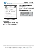
EIA JEDEC standard J-STD-020 level 3 label

is included on all dry bags

ESD PRECAUTION

Proper storage and handling procedures should be followed 
to prevent ESD damage to the devices especially when they 
are removed from the antistatic shielding bag. Electrostatic 
sensitive devices warning labels are on the packaging.

VISHAY SEMICONDUCTORS STANDARD


BAR CODE LABELS

The Vishay Semiconductors standard bar code labels are 
printed at final packing areas. The labels are on each 
packing unit and contain Vishay Semiconductors specific 
data.

BAR CODE PRODUCT LABEL 

(example)

1. Calculated shelf life in sealed bag: 12 months at <40°C and <90%
  relative humidity (RH)

3. After bag is opened, devices that will be subjected to reflow solder or other high
  temperature process must be

4. Devices require bake, before mounting, if:

  a) Humidity Indicator Card reads > 10% for level 2a - 5a devices or >60% for
  level 2 devices when read at 23±5°C

  b) 3a or 3b are not met

5. If baking is required, refer to IPC/JEDEC J-STD-033 for bake procedure

2. Peak package body temperature:_______________________°C

If blank, see adjacent bar code label

  a) Mounted within:___________________hours of factory conditions

  ≤30°C/60% RH, or
  b) Stored per J-STD-033

If blank, see adjacent bar code label

Bag Seal Date:_________________________________________

If blank, see adjacent bar code label

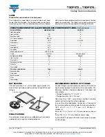
Note: Level and body temperature defined by IPC/JEDEC J-STD-020

This bag contains

MOISTURE-SENSITIVE DEVICES

Caution

If blank, see adjacent

bar code label

3

LEVEL

260

168

22650

22178

Summary of Contents for TSOP57236

Page 1: ...ier are assembled on a PCB the epoxy package contains an IR filter The demodulated output signal can be directly connected to a microprocessor for decoding The TSOP572 TSOP574 are optimized to suppress almost all spurious pulses from energy saving lamps like CFLs The AGC4 used in the TSOP574 may suppress some data signals The TSOP572 is a legacy product for all common IR remote control data format...

Page 2: ...mponents R1 and C1 are optional to improve the robustness against electrical overstress typical values are R1 100 Ω C1 0 1 µF ABSOLUTE MAXIMUM RATINGS PARAMETER TEST CONDITION SYMBOL VALUE UNIT Supply voltage VS 0 3 to 6 V Supply current IS 5 mA Output voltage VO 0 3 to VS 0 3 V Output current IO 5 mA Junction temperature Tj 100 C Storage temperature range Tstg 25 to 85 C Operating temperature ran...

Page 3: ...d 1 tpo 2 1 7 f0 td 15 f0 2 tpi 5 f0 tpo tpi 6 f0 1 0 0 2 0 3 0 4 0 5 0 6 0 7 0 8 0 9 0 1 1 10 102 103 104 Ee Irradiance mW m2 t po Output Pulse Width ms Input Burst Length Output Pulse Width λ 950 nm Optical Test Signal Fig 1 0 0 1 Ee t VO VOH VOL t 600 µs 600 µs t 60 ms ton toff 94 8134 Optical Test Signal Output Signal see fig 4 0 0 1 0 2 0 3 0 4 0 5 0 6 0 7 0 8 0 1 1 10 102 103 104 105 Ee Irra...

Page 4: ... 0 8 0 9 1 0 1 10 100 1000 ΔVsRMS AC Voltage on DC Supply Voltage mV E e min Threshold Irradiance mW m 2 f f0 f 20 kHz f 30 kHz f 100 Hz f 10 kHz 0 0 1 0 2 0 3 0 4 0 5 0 6 0 7 0 8 0 20 40 60 80 100 120 Burst Length number of cycles burst Max Envelope Duty Cycle f 38 kHz Ee 2 mW m2 TSOP572 TSOP574 21396_15 Tamb Ambient Temperature C E e min Sensitivity mW m 2 0 0 05 0 10 0 15 0 20 0 40 30 10 10 30 ...

Page 5: ...ht Continuous signals at any frequency Strongly or weakly modulated patterns from fluorescent lamps with electronic ballasts see figure 12 or figure 13 Fig 13 IR Signal from Fluorescent Lamp with Low Modulation Fig 14 IR Signal from Fluorescent Lamp with High Modulation Notes For data formats with short bursts please see the datasheet for TSOP573 Best choice of AGC for some popular IR codes TSOP57...

Page 6: ...GND Out Vs Vs GND GND GND 0 75 0 05 4 x 0 75 3 0 35 0 05 8 x 1 5 3 0 3 0 3 0 3 0 7 1 9 3 4 Not indicated tolerances 0 1 specifications according to DIN technical drawings All dimensions in mm Drawing No 6 550 5315 01 4 Issue 2 12 02 14 marking area Drawing refers to following types TSOP37 TSOP57 Proposed pad layout from component side dim for reference only 3 95 3 95 0 35 0 8 2 75 3 4 x 4x 1 2 3 4...

Page 7: ...re at the device surface Since there is a temperature difference between the component and the circuit board it should be verified that the temperature of the device is accurately being measured Handling after reflow should be done only after the work surface has been cooled off Manual Soldering Use a soldering iron of 25 W or less Adjust the temperature of the soldering iron below 300 C Finish so...

Page 8: ...eters Leader and trailer tape Parts mounted Empty trailer 200 mm min Empty leader 400 mm min Direction of pulling out Unreel direction Ø 60 min Ø Y 2 0 5 Label posted here coming out from reel Tape position 12 4 18 4 max Ø 13 0 2 Ø 21 0 8 100 mm min with cover tape X 2 1 Tape and reel dimensions 2 1 75 5 5 12 0 3 8 4 Ø 1 5 0 3 Reel size Y TT1 Ø 180 2 1800 pcs TT2 Ø 330 2 7000 pcs 1 2 Technical dra...

Page 9: ...een opened to prevent moisture absorption The following conditions should be observed if dry boxes are not available Storage temperature 10 C to 30 C Storage humidity 60 RH max After more than 168 h under these conditions moisture content will be too high for reflow soldering In case of moisture absorption the devices will recover to the former condition by drying under the following condition 192...

Page 10: ...specific data BAR CODE PRODUCT LABEL example 1 Calculated shelf life in sealed bag 12 months at 40 C and 90 relative humidity RH 3 After bag is opened devices that will be subjected to reflow solder or other high temperature process must be 4 Devices require bake before mounting if a Humidity Indicator Card reads 10 for level 2a 5a devices or 60 for level 2 devices when read at 23 5 C b 3a or 3b a...

Page 11: ...mer application by the customer s technical experts Product specifications do not expand or otherwise modify Vishay s terms and conditions of purchase including but not limited to the warranty expressed therein Except as expressly indicated in writing Vishay products are not designed for use in medical life saving or life sustaining applications or for any other application in which the failure of...

Reviews: