background image

DE

33

MIDI-Pedalboard

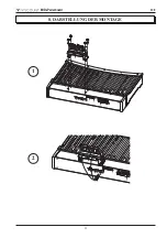
8. DARSTELLUNG DER MONTAGE

MIDI-Pedalboard

EXPR. 2 EXPR.

1

MIDI

OUT

INPUT 2 INPUT

1

SET

POWER

AC-IN

RISK OF ELECTRIC

SHOCK

DO NOT OPEN

RISQUE DE CHOC

ELECTRIQUE

NE PAS OUVRIR

TO REDUCETHE

RISK OF FIREOR

ELECTRIC SHOCK

, DO NOT EXPOSE

THIS APPLIANCE

TO RAIN OR MOIS

TUR

`

THIS DEVICE

COMPLIES WITH

PART 15 OF THE

FCC RULES

. OPERATION IS

SUBJECT

TO THE FOLLOWING

TW

CONDITIONS:

1.THIS DEVICE

MAY NOT CAUSE

HARMFUL INTERF

ERENCE,AND

2.THIS DEVICE

MUST ACCEP

T

ANY INTERF

ERENCE

RECEIVED,

INCLUDING

INTERFERENCE

THAT MAY CAUSE

UNDESIRED

OPERATION.

UTILISER UN FUSIB

LE DE

DEBRANCHERAVA

NT

DE REMPLACERL

E FUSIBLE

RECHANGE DEM

EME TYPE

ATTENTION

FOR CONTINUED

PROTECTION

AGAINST FIREHA

ZARD REPLACE

ONLY WITH SAME

TYPE FUSES

DISCONNECTSUP

PLY CORD

BEFORE CHANGIN

G FUSE

CAUTION

FUSE

T0,2A L250V FOR

MAINS 100 -240

T0,2A L250V FOR

MAINS 100 -240

T0,2A L250V FOR

MAINS 100 -240

MIDI-Pedalboard

EXPR. 2 EXPR.

1

MIDI

OUT

INPUT 2 INPU

T 1

SET

POWER

AC-IN

RISK OF ELECTR

IC SHOCK

DO NOT OPEN

RISQUE DE CHOC

ELECTRIQUE

NE PAS OUVRIR

TO REDUCETHE

RISK OF FIRE OR

ELECTRIC SHO

CK, DO NOTEXPO

SE THISAPPLIAN

CE TO RAIN OR

MOISTURE.

`

THIS DEVICE CO

MPLIES WITH PA

RT 15 OF THE FC

C RULES. OPERA

TION IS SUBJECT

TO THE FOLLOW

ING TW0

CONDITIONS:1.T

HIS DEVICE MAY

NOT CAUSE HAR

MFUL INTERFER

ENCE,AND 2.THIS

DEVICE MUSTAC

CEPT

ANY INTERFERE

NCE RECEIVED,

INCLUDING INTE

RFERENCE THAT

MAY CAUSE UND

ESIRED OPERAT

ION.

UTILISER UN FUSIB

LE DE

DEBRANCHERAVA

NT

DE REMPLACER

LE FUSIBLE

RECHANGE DEM

EME TYPE

ATTENTION

FOR CONTINUED

PROTECTION

AGAINST FIREHA

ZARD REPLACE

ONLY WITH SAM

E TYPE FUSES

DISCONNECTSU

PPLY CORD

BEFORE CHANGI

NG FUSE

CAUTION

FUSE

T0,2A L250V FOR

MAINS 100 -240V

T0,2A L250V FOR

MAINS 100 -240V

T0,2A L250V FOR

MAINS 100 -240V

1

2

Summary of Contents for Midi

Page 1: ...Manuale d uso IT User Manual EN Bedienungsanleitung DE Ver 1 2 MIDI Pedalboard ...

Page 2: ......

Page 3: ...onnettori del pannello posteriore 2 2 Normale funzionamento 3 3 Configurazione dello strumento modalità Set 4 4 Funzioni di configurazione 5 5 Midi Bulk Dump 7 6 Caricamento del sistema operativo 8 7 Factory Setting 8 8 Schema di assemblaggio 9 ...

Page 4: ...roveniente dal pedale sinistro 3 MIDI OUT connettore Midi dal quale vengono trasmessi i dati generati dalla pedaliera e quelli ricevuti dalle due prese Midi INPUT 4 INPUT 2 seconda presa Midi di ingresso alla quale collegare un generatore di dati Midi esterno 5 INPUT 1 prima presa Midi di ingresso alla quale collegare un generatore di dati Midi esterno 6 Led verde led di visualizzazione dei dati M...

Page 5: ... inviare i dati Midi generati dallo strumento ritrasmette anche quelli ricevuti dalle due porte INPUT 1 e INPUT 2 funzione Soft Thru ESEMPI DI UTILIZZO Grazie a questo funzionamento è possibile utilizzare la pedaliera Midi in diverse modalità ad esempio Pedaliera per organo che non ne è equipaggiato EXPR 2 EXPR 1 MIDI OUT INPUT 2 INPUT 1 SET MIDI IN Organ Keyboard etc MIDI Pedalboard Pedaliera e M...

Page 6: ...Fa 1 canale Midi di trasmissione della note suonate con la pedaliera Sol 1 valore della dinamica Midi delle note suonate con la pedaliera La 1 numero della nota Midi o del messaggio di Program Change del primo pedale funzione transposer Do 2 canale Midi di trasmissione del messaggio di Control Change associato al pedale di espres sione EXPR 1 Re 2 canale Midi di trasmissione del messaggio di Contr...

Page 7: ...1 Premere il pulsante SET 2 Premere il Sol 1 3 Premere il Do 1 4 Premere un pedale bianco da 0 a 9 il Do1 corrisponde allo 0 5 Premere il Re 1 6 Premere un pedale bianco da 0 a 12 il Do1 corrisponde allo 0 7 Premere il Do 3 NUMERO DI NOTA O PROGRAM CHANGE ASSOCIATO AL PRIMO PEDALE Quando la pedaliera è in modalità note vedi par Impostazione della modalità di pedaliera questa funzione imposta il nu...

Page 8: ... SET 2 Premere il Fa 2 3 Premere il Mi1 e posizionare il pedale d espressione nella posizione minima 4 Premere il Do 3 5 Premere il pulsante SET 6 Premere il Fa 2 7 Premere il Fa1 e posizionare il pedale d espressione alla posizione massima 8 Premere il Do 3 CONTROL CHANGE TRASMESSO DAL PEDALE D ESPRESSIONE EXPR 2 1 Premere il pulsante SET 2 Premere il Sol 2 3 Premere il Do1 per assegnare il Contr...

Page 9: ... INPUT 2 della pedaliera Midi Una volta effettuati i collegamenti premere il pulsante SET e avviare la trasmissione dal dispositivo Midi esterno Al termine della ricezione lo strumento esegue una verifica dei dati onde evitare di rendere inutilizzabile la pedaliera passata la quale il Bulk Dump ricevuto viene memorizzato a conferma di ciò il Led rosso si spegne Qualora i dati ricevuti non sono cor...

Page 10: ...ne fornito tramite un file Midi file mid Per caricare lo stesso nella pedaliera è necessario disporre di un lettore Midi la cui porta Midi Out è da collegare alla INPUT 1 no la INPUT 2 della pedaliera Durante la ricezione dei dati il led verde lampeggia al temine del caricamento viene eseguita una verifica dei dati passata la quale il Led verde si spegne e quello rosso lampeggia una volta Qualora ...

Page 11: ...FORE CHANGIN G FUSE CAUTION FUSE T0 2A L 250V FOR MAINS 100 240 T0 2A L 250V FOR MAINS 100 240 T0 2A L 250V FOR MAINS 100 240 MIDI Pedalboard EXPR 2 EXPR 1 MIDI OUT INPUT 2 INPUT 1 SET POWER AC IN RISK OF ELECTRIC SHOCK DO NOT OPEN RISQUE DE CHOC ELECTRIQU E NE PAS OUVRIR TO REDUCE THE RISK OF FIRE OR ELECTRIC SHOCK DO NOT EXPOSE THIS APPLIANCE TO RAIN OR MOISTURE THIS DEVICE COMPLIES WITH PART 15...

Page 12: ...e il prodotto venga smaltito in modo adeguato eviterete un potenziale impatto negativo sull ambiente e la salute umana che potrebbe essere causato da una gestione non conforme dello smaltimento del prodotto Il riciclaggio dei materiali contribuirà alla conservazione delle risorse naturali Per ricevere ulteriori informazioni più dettagliate Vi invitiamo a contattare l uffi cio preposto nella Vostra...

Page 13: ......

Page 14: ......

Page 15: ...EX 1 Controls and connections on the rear panel 14 2 Play mode 15 3 Instrument configuration Set mode 16 4 Configuration functions 17 5 Midi Bulk Dump 19 6 Operating system updating 20 7 Factory Setting 20 8 Assembly scheme 21 ...

Page 16: ...ssion pedal 3 MIDI OUT Midi socket for the transmission of the Midi data generated by the pedalboard and received by the two INPUT Midi sockets 4 INPUT 2 second Midi input socket for the connection of an external Midi data generator 5 INPUT 1 first Midi input socket for the connection of an external Midi data generator 6 Green led Led showing Midi data transmission on MIDI OUT 7 Red led Led showin...

Page 17: ...ission also transmits the Midi data received through INPUT 1 and INPUT 2 Soft Thru function Midi sockets EXAMPLES This function permits to use the Midi pedalboard in different ways i e with organs not equipped with a pedalboard EXPR 2 EXPR 1 MIDI OUT INPUT 2 INPUT 1 SET MIDI IN Organ Keyboard etc MIDI Pedalboard to use the Pedalboard and Midi Thru with an external sound generator EXPR 2 EXPR 1 MID...

Page 18: ...edalboard G 1 Midi velocity value of the notes played on the pedalboard A 1 Midi note or Program Change number of the first pedal C1 transposer function C 2 Midi transmission channel for Control Change in connection with the expression pedal EXPR 1 D 2 Midi transmission channel for Control Change in connection with the expression pedal EXPR 2 F 2 function connected type of Control Change transmitt...

Page 19: ...S 1 Press the SET button 2 Press G 1 3 Press C 1 4 Press a white key from 0 to 9 C1 corresponds to 0 5 Press D 1 6 Press a white key from 0 to 12 C1 corresponds to 0 7 Press C 3 NOTE NUMBER OR PROGRAM CHANGE CONNECTED TO THE FIRST PEDAL When the pedalboard is in note mode see also par Pedalboard function mode it will set the note number of the first key This function allows the adjustment of a tra...

Page 20: ...ON 1 Press SET button 2 Press F 2 3 Press E1 and set the expression pedal at minimum 4 Press C 3 5 Press SET button 6 Press F 2 7 Press F1 and set the expression pedal at maximum 8 Press C 3 CONTROL CHANGE TRANSMITTED BY THE EXPRESSION PEDAL EXPR 2 1 Press SET button 2 Press G 2 3 Press C1 to assign Control Change 7 Volume or D1 Control Change 11 Expression 4 Press C 3 EXPRESSION PEDAL EXPR 2 CALI...

Page 21: ...sly transmitted and recorded connect the Midi Out of a Midi data player or a sequencer to Midi pedalboard s INPUT 1 or INPUT 2 Then press SET button and start playing the recorded Midi Bulk Dump on the external Midi device When reception is terminated the instrument will check datas in order to avoid configuration problems If they are not correct the red Led will flash twice 7 Press C 3 PEDALBOARD...

Page 22: ... OPERATING SYSTEM UPDATING The operating system is supplied by Viscount as a Midi file mid file For loading it into the Midi pedalboard you have to use a Midi data player and to connect its Midi out to the pedalboard s INPUT 1 not INPUT 2 When loading the green Led will flash after reception the instrument will check data If correct the green Led lights off and the red Led will flash one time If n...

Page 23: ...E CHANGIN G FUSE CAUTION FUSE T0 2A L 250V FOR MAINS 100 240 T0 2A L 250V FOR MAINS 100 240 T0 2A L 250V FOR MAINS 100 240 MIDI Pedalboard EXPR 2 EXPR 1 MIDI OUT INPUT 2 INPUT 1 SET POWER AC IN RISK OF ELECTRIC SHOCK DO NOT OPEN RISQUE DE CHOC ELECTRIQU E NE PAS OUVRIR TO REDUCE THE RISK OF FIRE OR ELECTRIC SHOCK DO NOT EXPOSE THIS APPLIANCE TO RAIN OR MOISTURE THIS DEVICE COMPLIES WITH PART 15 OF...

Page 24: ...n which can be determinated by turning the equipment off and on the user is encuraged to try to correct the interference by one or more of the following measures Reorient or relocate the receiving antenna Increase the separation between the equipment and receiver Connect the equipment into an outlet on a circuit different from that to which the receiver is connected Consult the dealer or an experi...

Page 25: ......

Page 26: ......

Page 27: ...nelemente und Aschlüsse auf der Rückseite 26 2 Normaler Gebrauch 27 3 Konfiguration des Instruments Einstellmodus 28 4 Konfigurationsfunktionen 29 5 Midi Bulk Dump 31 6 Laden des Betriebssystems 32 7 Werkeinstellungen 32 8 Darstellung der Montage 33 ...

Page 28: ...hwellers 3 MIDI OUT Midi Buchse für die Übertragung der Midi Daten die vom Midi Pedal selbst erzeugt werden und derjenigen die an den beiden Midi Buchsen INPUT empfangen werden 4 INPUT 2 Zweite Midi Eingangsbuchse für den Anschluss eines externen Midi Datenerzeugers 5 INPUT 1 Erste Midi Eingangsbuchse für den Anschluss eines externen Midi Datenerzeugers 6 Green led LED für die Anzeige der Übertrag...

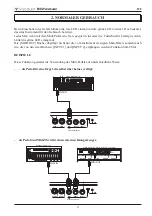
Page 29: ...m Instrument erzeugten Midi Daten sondern auch die die von den zwei Buchsen INPUT 1 und INPUT 2 empfangen werden Funktion Soft Thru BEISPIELE Diese Funktion gestattet die Verwendung des Midi Pedals auf unterschiedliche Weise als Pedal für eine Orgel die selbst über keines verfügt EXPR 2 EXPR 1 MIDI OUT INPUT 2 INPUT 1 SET MIDI IN Organ Keyboard etc MIDI Pedalboard als Pedal und Midi Thru für einen...

Page 30: ... der Eingabe von numerischen Daten von 0 bis 127 D 1 Zehnerstelle bei der Eingabe von numerischen Daten von 0 bis 127 F 1 Midi Übertragungskanal für die mit dem Pedal gespielten Noten G 1 Wert der Midi Dynamik der mit dem Pedal gespielten Noten A 1 Nummer der Midi Note oder des Program Change Befehls der ersten Taste C1 Transpositionsfunktion C 2 Midi Übertragungskanal für den Control Change Befeh...

Page 31: ...2 Drücken Sie G 1 3 Drücken Sie C 1 4 Drücken Sie eine weiße Taste von 0 bis 9 C1 entspricht 0 5 Drücken Sie D 1 6 Drücken Sie eine weiße Taste von 0 bis 12 C1 entspricht 0 7 Drücken Sie C 3 DER ERSTEN TASTE ZUGEWIESENE MIDI NOTEN ODER PROGRAM CHANGE NUMMER Wenn sich das Midi Pedal im Noten Modus befindet siehe den Abs Einstellung des Funktionsmodus des Midi Pedals kann man mit dieser Funktion die...

Page 32: ... SET 2 Drücken Sie F 2 3 Drücken Sie E1 und bringen Sie den Fußschweller in die Minimum Stellung 4 Drücken Sie C 3 5 Drücken Sie die Taste SET 6 Drücken Sie F 2 7 Drücken Sie F1 und bringen Sie den Fußschweller in die Maximum Stellung 8 Drücken Sie C 3 VOM FUSSSCHWELLER EXPR 2 ÜBERTRAGENER CONTROL CHANGE 1 Drücken Sie die Taste SET 2 Drücken Sie G 2 3 Drücken Sie C1 um den Control Change 7 Volume ...

Page 33: ...nen zu erstellen die Sie jederzeit wiederherstellen und nutzen können Mit dieser Funktion können Sie außerdem eine Sicherheitskopie der Konfiguration des Midi Pedals für den Fall erstellen dass sein interner Speicher beschädigt oder versehentlich gelöscht wird ÜBERTRAGUNG Zum Übertragen der Konfiguration des Instruments über denAnschluss MIDI OUT der an denAnschluss MIDI IN eines Midi Aufnahmegerä...

Page 34: ...al wird ein Midi Abspielgerät benötigt dessen Anschluss Midi Out mit dem Anschluss INPUT 1 nicht INPUT 2 des Midi Pedals zu verbinden ist Während des Empfangs der Daten blinkt die grüne LED Nach dem Laden werden die Daten geprüft Ist das Ergebnis der Prüfung positiv erlischt die grüne LED und die rote LED blinkt einmal Bei negativem Ausgang der Prüfung signalisiert die rote LED den Fehler durch ei...

Page 35: ...EFORE CHANGIN G FUSE CAUTION FUSE T0 2A L 250V FOR MAINS 100 240 T0 2A L 250V FOR MAINS 100 240 T0 2A L 250V FOR MAINS 100 240 MIDI Pedalboard EXPR 2 EXPR 1 MIDI OUT INPUT 2 INPUT 1 SET POWER AC IN RISK OF ELECTRIC SHOCK DO NOT OPEN RISQUE DE CHOC ELECTRIQU E NE PAS OUVRIR TO REDUCE THE RISK OF FIRE OR ELECTRIC SHOCK DO NOT EXPOSE THIS APPLIANCE TO RAIN OR MOISTURE THIS DEVICE COMPLIES WITH PART 1...

Page 36: ...nkt zum Recyclen von Elektro und Elektronikgeräten gebracht werden Wird das Produkt korrekt entsorgt helfen Sie mit negativen Umwelteinfl üssen und Gesundheitsschäden vorzubeugen die durch unsachgemäße Entsorgung verursacht werden könnten Das Recycling von Material wird unsere Naturressourcen erhalten Für nähere informationen über das Recyclen dieses Produktes kontaktieren Sie bitte Ihr lokales Bü...

Page 37: ...SYSTEM Clock 1 REAL TIME Commands AUX Local On Off 1 MESSAGES All notes off Active Sense Reset NOTES 1 Midi data received by Input ports are redirected to the Midi Out port 2 a fixed velocity value can be setted in Set mode see chapt 4 Mode 1 Omni On Poly Mode 2 Omni On Mono O YES Mode 3 Omni Off Poly Mode 4 Omni Off Mono X NO MIDI IMPLEMENTATION CHART FUNCTION TRANSMITTED RECEIVED 1 16 1 16 1 16 ...

Page 38: ......

Page 39: ......

Page 40: ...Viscount International S p A Via Borgo 68 70 47836 Mondaino RN ITALY Tel 39 0541 981700 Fax 39 0541 981052 Website www viscountinstruments com ...

Reviews: