background image


17 

Changes can be made without prior noticy. All rights reserved. 
© Viscoo Enterprises Ltd. – 

www.viscoo.nl


4.4 Output settings 

4.4.1 Screen settings 

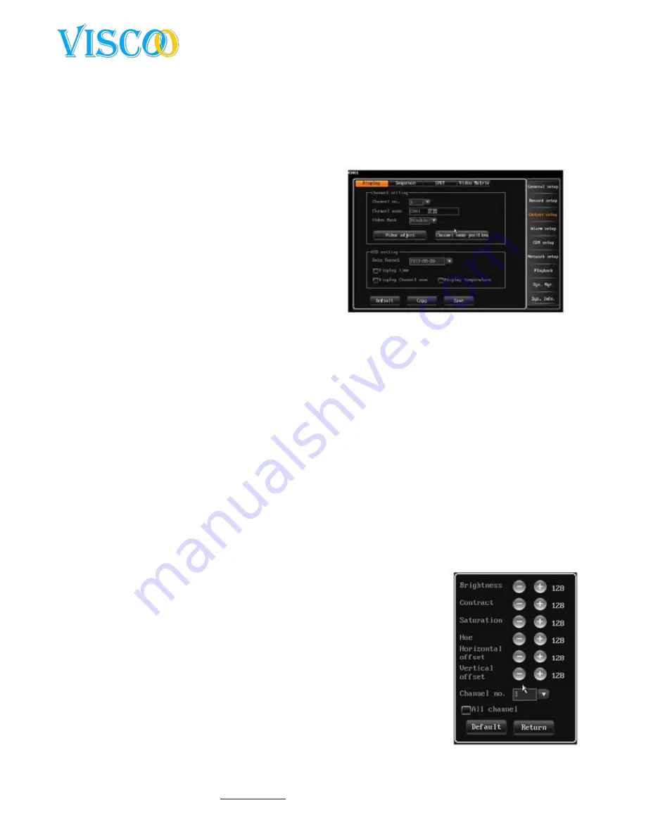
After logging in one chooses “main menu” and then”output setup” -> “display setup”, use the screen 
as follows: 

These settings are used to channel parameters such 
as name, mask video, video settings, v=channel 
name, position and OSD settings.  

1.


Channel name: 


The channel name can be up to 16 
chinese characters and up to 32 english 
characters and numbers. 


Customize the Mouse: double-click to 
open the keyboard. Click on AND to show 
the english entry. 


Change the remote control: press # to change the input method. 


Channel name is fixed to the upper left side of the channel, the channel name position 
can be changed by dragging it to the position that is prefered. 


When the channel settings are beeing copied the channel name will be left out. 

Mask area settings: 

In some cases of recordings, user sensitive or private areas of the camera screen can be masked, for 
example the position of the pincode input on a ATM. 

Each channel support up to 4 masked areas.  


Turn on the video mask setting to use this feature. Click on the video area to highlight mask 
settings and adjust. 


Click the left button to the left corner and then to the right corner. 


Set with remote controler; press the direction key to move the cursor, press “ok” to give in 
the start position. Then move the cursor to the end position and press”ok”again. Press 
“clear” to remove the selected area. 


Back to the interface channel settings and press save to store 
changed data. 


The selected area is active in the live and manual recording modes. 

2.


Video settings 

After logging in one chooses “display setup” and then ‘video para”or use 
right click Mouse and then click on “image”. 


Standard video parameters: brightness(128), contrast(128), 
saturation(128) and hue(128). 


Channel nr: used to switch channels, all channel scan be usede 
directly. 

Adjustment method: 

Summary of Contents for VIS304

Page 1: ...English User Manual Viscoo Enterprises Ltd October 2011 ...

Page 2: ... this series different product models configuration will have a little difference and their might be differences between product functionality and operation This manual can only be used for reference We will not provide any new information separately for later firmware updates The updating files will be added into the new edition of the user manual and it will also be posted our website in the dow...

Page 3: ...rm Input Output connection 8 3 5 The frontpanel 9 3 6 Mouse controle 10 3 7 IR remote controle 10 3 8 Menu description 11 4 Operation of the unit 13 4 1 Power on in and out logging outlogging 13 4 1 1 Keystroke in outlogging 13 4 1 2 Log into the system 14 4 1 3 Log out of the system 14 4 1 4 Mainmenu 14 4 2 General settings of the recorder 14 4 2 1 General settings 14 4 2 2 Time setup 15 4 3 Reco...

Page 4: ...p control 25 4 9 3 Hard disk Management 25 4 9 4 Back to default settings 26 4 10 System Informatie 26 4 10 1 System Informatie 26 4 10 2 Recording status 26 4 10 3 Alarm Status 26 4 10 4 Online Status 27 4 10 5 Log Information 27 4 11 Software Upgrade 27 4 11 1 Client Software Upgrade 27 4 11 2 USB Upgrade 28 4 12 Restoration after power outage 28 Appendix 1 Internet Explorer operation instructio...

Page 5: ...e and dedicated DVR file system It won t create the disk defragment in a long run Logical stream media operation fast response Add the key information verify protection avoid the key area of the HDD damage This DVR system supports USB2 0 high speed backup mouse keyboard operation etc 1 2 Product introduction Model VIS304 VIS308 VIS316 Housing 1 U Operation System Linux Video Format 1 D1 3 CIF 1 Ch...

Page 6: ...ut Audio Input 8 ch audio ingang 16 ch audio ingang 8 ch audio ingang Audio Output 1 BNC audio Output Microphone 3 5mm MIC Interface Total Frames PAL 200 fps NTSC 240 fps PAL 400 fps NTSC 480 fps PAL 600 fps NTSC 720 fps Compression Video H 264 Audio G 711A Recording Resolution CIF 352 X 288 PAL 25fps 352 X 240 NTSC 30fps D1 704 X 576 PAL 6fps 704 X 480 NTSC 7fps Live Resolution BNC D1 704 X 576 P...

Page 7: ...the power adapter is stable prevents an abnormale voltage drop Make sure no pieces of metal or liquids fall into the unit this can cause a short circuit The unit will not record when no hard disk is present in the device Make sure you also keep the machine clean inside this will expend the lifetime Don t connect or disconnect devices with the unit on this prevents damage to the unit If you turm of...

Page 8: ...device larger then 512Mb and FAT32 formatted 3 3 Netwerk Interface There is an RJ45 10M 100M adaptive ethernet interface available that allows the DVR to connect to your PC or network The ACT and LINK led s indicate the status by the following Link network speed indicator from to 100M 10M ACT sending and receiving indicator flasking means it will receive and send data If the you connect the DVR di...

Page 9: ...n PTZ mode this means iris Clear Iris 1 Add and remove 2 Alarm reset 3 When in PTZ mode this means iris Up Focus Menu up When in PTZ mode this means focus Down Focus Menu down When in PTZ mode this means focus Return Wiper Back to menu before When in PTZ mode this means wiper use 3 Indication lights Power If this light is green it means that the device is in operation mode the light turns amber it...

Page 10: ...y logged in the result is a shortend menu that will be displayed If you are not logged in the password screen will appear here please enter 888888 This is the deafault password The deafault username is admin If you are in a menu and you press the right Mouse button you will return to the menu before When you enter the date you get a software keyboard then press the right Mouse button it will disap...

Page 11: ...Log Off 29 F1 4 Focus 17 Information 30 PTZ 5 rewind 18 Backup 31 Server Index 6 forward 19 Image iris 32 2 ABC 7 Ok play and pause 20 Shift Zoom 33 1 8 back 21 Clear iris 34 5 JKL 9 F2 22 Format zoom 35 4 GHI 10 Auto 23 Record 36 8 TUV 11 Wiper 24 up Slow Motion 37 7 PQRS 12 3 DEF 25 left en backwards 38 0 13 6 MNO 26 go down and frame forwards 39 Preset 3 8 Menu description Menu Instruction ...

Page 12: ...ideo marking 3 Channel doubling 4 Date setup 5 Different OSD setup 6 Video parameters 7 Video input adjustment Sequence settings Several sequence settings for live display Video Matrix Matrix settings Alarm Setup Motion detection 1 Alarm schedule 2 Sensitivity levels 1 tot 5 5 is the highest 3 Detection area settings 4 Video loss alarm 5 Channel doubling Sensor detection 1 Sensor ID 2 Alarm schedu...

Page 13: ...own device Sound mute Turn of sound Restart Restart the DVR USB Update Update theDVR 4 Device control 4 1 Power on log in out log off Power on when you have connected the power cable the light indicator will turn on to its standby status After pushing the power button on the remote controler for 3 seconds the DVR will turn on Power down when the system is running press the power button on the remo...

Page 14: ...to a personal code 4 1 3 log out of the system and autolock When logged into the system and the automatic logoff time is exeeced the system will automaticly log off The settings for the auto logoff time can be configured in the general settings tab of the recorder One can also use the login lock button on the remote control or by right clicking on the Mouse 4 1 4 Main menu When the user succesfull...

Page 15: ...ou can use this feature 1 The system support 26 timezones to be set according to the timezone that applies to the location of the recorder 2 Its is not recommend to change the default server adress 3 Ports and timezones are optional 4 The system is automaticly set to the time interval that the user has selected 5 The DVR needs access to the internet to activate the NTP 4 3 Recording settings 4 3 1...

Page 16: ...recording features the standard pre recording time is 10 seconds The adjustable range is from 0 to 30 seconds Partly because of the VBR variable bit rate the final pre recording time differs from the one set Delayed recording time the recording time after a sensor or other alarm is triggered default duration is 30 seconds The range is from 0 to 180 seconds 4 3 2 Manual recording After logging in c...

Page 17: ... left out Mask area settings In some cases of recordings user sensitive or private areas of the camera screen can be masked for example the position of the pincode input on a ATM Each channel support up to 4 masked areas Turn on the video mask setting to use this feature Click on the video area to highlight mask settings and adjust Click the left button to the left corner and then to the right cor...

Page 18: ...nnel numbers sequencing and sequence interval division Speedy choose The interface looks like this Sequence format 1ch 4ch 9ch screen Sequence Channel Number The user can set channel number sequence the sequence channel number must be greater than the selected division Sequence interval time range is 3 to 60 seconden Note The sequence function is only active when the system is in lock status 4 5 A...

Page 19: ...6 Alarm Output Setup The button will turn yellow when the alarm output function is activated with deactivation the button is gray 2 Video loss alarm By default the DVR is set when a signal interruption occurs an alarm buzzer is activated There are 3 ways to set an alarm output these are audio buzzer and full screen You can click on information to see the emergency status 4 5 2 Alarm Sensor setup T...

Page 20: ... outputtime inspection 2 300s the standaard is 30 seconds Alarm active time the standard schedule is 00 00 23 59 for every day 4 5 4 Email Setup After logging in it goes through main menu to Alarm Setup then to Email Setup to go the interface looks like this Email setup settings 1 Activate the Email upload select the related email On alarm video loss motion detection sensor detection trigger the D...

Page 21: ...th this option it must correspond to the PTZ camera 4 6 2 PTZ The procedure for PTZ settings Select the type of COM COM device and baud rate in the setup COM interface Enter the PTZ setup interface to the protocol and address of the camera settings usually the first PTZ address 1 Note PTZ protocol baud rate address must be equal to that which is in the PTZ camera Switch to the channel for single c...

Page 22: ...Enter the DNS address obtained from the PPPOE provider here possibly the gateway address in this box When using DDNS this should be correct If no DNS is given you can always use the Google DNS 8 8 8 8 and 8 8 4 4 Command port This is the data transmission port for the client software default is 8101 port range 8000 HTTP port IE browse port default is port 81 Port be changed you do need to restart ...

Page 23: ...ch as IP address and subnet Press the save button to store data Next time the recorder automatically connecting to the network Note You must manually connect to the network when you select auto re dial on 4 8 Playback The system knows two ways to open and recall the playback menu screen 1 Open the playback interface press the play button on the front panel or remote control Click on the yellow ico...

Page 24: ...ment screen is shown 4 9 1 User Management When the DVR leaves the factory the user and password settings are in default state Using for user admin and for the password 888888 Please changes these settings for security reasons The admin has the most rights of all the users and he can make a maximum of 15 other users All the rights of the users are admited by the admin For protrection and security ...

Page 25: ...me of the host After setting up the hostname the user can save save button to confirm Note The host name can comprise up to 32 characters 2 Backup files playback To play back the backup files the user needs to open the playback interface and push on the inquire button select the file and press enter to play Backup date Displays the backup files in the current hard disk partition backup Move the cu...

Page 26: ... stream 512K recording quality High video frame 25 Audio Enabled Transmission encoding stream 512K Transmission image quality high Transmission Audio enabled Record Mode Manual closed diagram closed Motion closed alarm detection closed Netwerk Auto redial closed Auto login closed COM Baudrate 9600 Data bit 8 Parity bit non Stop bit 1 Keyboard adres 1 Protocol unknown Channel channel names reset to...

Page 27: ...m log PTZ control log users and log out log changes in system parameters recording playback log backup log format HDD log user login client log etc 4 11 Software Upgrade There are two ways to upgrade your digital video recorder 1 The PC client software 2 Via a USB stick directly on the recorder Read the following information carefully before you start an upgrade 4 11 1 Client Software Upgrade Plea...

Page 28: ...n is as before 4 11 2 USB Upgrade The USB upgrade is as follows 1 Copy the upgrade bin to the USB stick 2 Insert the USB stick into the USB port on the back of the recorder it will automatically be recognized and notifide Then go to system information and click interface USB upgrade Then press to confirm the update process 3 The system now states the system is updating 4 When the upgrade is comple...

Page 29: ...ace method replace the power supply and hard disk recorder 2 Minimum load method switch off all the recordings and alarms 3 Upgrade lets you solve the compatibility problems Notes Some problems may arise by incorrect use of the recorder You can restore to factory defaults procedure Problems related to power up selftest en system interuptions Why will the DVR not start while it is on the power supp...

Page 30: ...tor 1 Check the screen settings of the monitor 2 Make sure the screen settings are adjusted to get full screen Why does my recorder show weird colors on my monitor 1 Check the VGA cable to the monitor apparently the DATA line cable is not in working order 2 Check if the recorder is not overheated I have successfully booted my system but there was an empty channel Try to reboot again if this does n...

Page 31: ... whether the area for motion detection has been activated 3 Check the sensitivity of the motion wether it is not too low Why can i not make alarm recordings 1 Make sure you have the alarm scheme changed and whether the current time is in the schedule 2 Check the alarm settings interface and make sure there all set correctly to the time tables 3 Check if the sensor is propperly connected Why are th...

Page 32: ...al devices such as PTZ and keyboard to the recorder 1 Connect the devices and to the parallel port and assign addresses correctly 2 Create an RS485 bus line linking the pluses and minuses to the correct input output of the recorder And once again set the addresses of the devices How do I remove alarms You can see on the front of the recorder on the button Clear button when you are logged You can a...

Reviews: