1
10
0
© 2005 Directed Electronics—all rights reserved
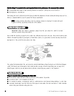
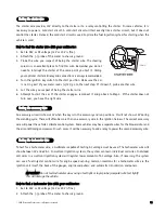
We recommend two possible sources for 12V constant: the (+) terminal of the battery, or the constant supply to the
ignition switch. Always install a fuse within 12 inches of this connection. If the fuse also will be powering other
circuits, such as door locks, a power window module, a Nite-Lite® headlight control system, etc., fuse accordingly.
IIM
MP
PO
OR
RTTA
AN
NTT!! Do not remove the fuse holder on the red wire. It ensures that the control module
has its own fuse, of the proper value, regardless of how many accessories are added to the main
power feed.
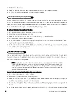
The ignition wire is powered when the key is in the run or start position. This is because the ignition wire powers
the ignition system (spark plugs, coil) as well as the fuel delivery system (fuel pump, fuel injection computer).
Accessory wires lose power when the key is in the start position to make more current available to the starter motor.
H
Ho
ow
w tto
o ffiin
nd
d ((+
+))1
12
2V
V iig
gn
niittiio
on
n w
wiitth
h yyo
ou
urr m
mu
ullttiim
meetteerr::
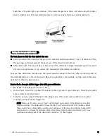
1. Set to DCV or DC voltage (12V or 20V is fine).
2. Attach the (-) probe of the meter to chassis ground.
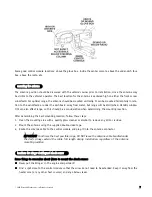
3. Probe the wire you suspect of being the ignition wire. The
steering column harness or ignition switch harness is an excel-
lent place to find this wire.
4. Turn the ignition key switch to the run position. If your meter
reads (+)12V, go to the next step. If it doesn’t, probe another
wire.
5. Now turn the key to the start position. The meter display should stay steady, not dropping by more than a
few tenths of a volt. If it drops close to or all the way to zero, go back to Step 3. If it stays steady at (+)12V,
you have found an ignition wire.
ffiinnddiinngg tthhee 1122VV ssw
wiittcchheedd iiggnniittiioonn w
wiirree
oobbttaaiinniinngg ccoonnssttaanntt 1122VV


