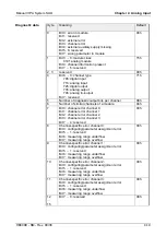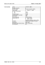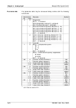
Manual VIPA System SLIO
Chapter 4 Analog Input
HB300E - SM - Rev. 09/38
4-17
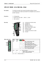
VIPA 031-1BD30 - AI 4x12Bit 0...10V
The electronic module has 4 inputs with parameterizable functions.
The channels of the module are isolated to the backplane bus by means of
DC/DC converters.
•
4 analog inputs
•
Suited for sensors with 0 ... 10V
•
12bit resolution
1
3
5
4
6
7
8
9
2
[1]
[2]
[3]
[4]
[5]
[6]
[7]
[8]
[9]
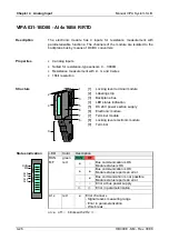
Locking lever terminal module
Labeling strip
Backplane bus
LED status indication
DC 24V power section supply
Electronic module
Terminal module
Locking lever electronic module
Terminal
LED
Color
Description
RUN green RUN
MF
MF red
●
○
Bus communication is OK
Module status is OK
●
●
Bus communication is OK
Module status reports an error
○
●
Bus communication is not possible
Module status reports an error
○
○
Error at bus power supply
☼
☼
Error in parameterization
Status indication
RUN
MF
AI 0
AI 1
AI 2
AI 3
AI x
red
●
Error channel x
- Signal leaves measuring range
- Error in parameterization
on:
●
off:
○
blinks with 2Hz:
☼
Description
Properties
Structure
Summary of Contents for 021-1BB00
Page 1: ...Manual VIPA System SLIO Signal modules SM Order No VIPA HB300E_SM Rev 09 38...
Page 2: ...L...
Page 6: ...Contents Manual VIPA System SLIO ii HB300E SM Rev 09 38...
Page 26: ...Chapter 1 Basics and Assembly Manual VIPA System SLIO 1 18 HB300E SM Rev 09 38...
Page 36: ...Chapter 2 Digital Input Manual VIPA System SLIO 2 10 HB300E SM Rev 09 38...
Page 44: ...Chapter 3 Digital Output Manual VIPA System SLIO 3 8 HB300E SM Rev 09 38...
Page 102: ...Chapter 5 Analog Output Manual VIPA System SLIO 5 24 HB300E SM Rev 09 38...


