background image

10

Crucial evidence. Always.

SLR-A75 Series

 | Solar Surveillance

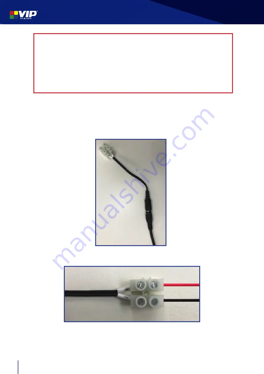
4.  Run the power cable coming from the solar panel through one of the cable holes of the junction 

box. 

5.  Carefully

 connect the solar panel power cable to the terminal block, with the 

red wire 

connecting to +

 and the 

black wire connecting to -

(Fig. 2.3f)

Fig. 2.3f 

Solar battery cables connected to terminal block

Fig. 2.3e 

Terminal block

Caution:

 Do not allow the negative and positive power supply wires from the solar 

panel to touch (short circuit)

 - this will cause the lithium polymer battery to enter protection 

mode and output voltage will drop to 0V.

The only way to recover from this is to disconnect and then reconnect the battery inside the 
panel - Please contact VIP Vision™ for further details.

When running cables, insulation should be removed from each end and cut carefully, 

ensuring each end does not touch each other.

Summary of Contents for SLR-A75 Series

Page 1: ...r purchasing a SLR A75 Series Solar Surveillance System This install guide covers basic setup installation and use of your surveillance system For more information please visit www vip vision com WiFi...

Page 2: ...e Mount Bracket VSBKTA150 1x 128GB microSD card MICROSD128GB 2x Ubiquiti 5 8GHz 120 Wireless Bridge 1x Access Point 1x Station WiFi system only WT5 ULB 1x Huawei 4G Modem Router with WiFi 4G system on...

Page 3: ...unction box The default username is admin Topreventunauthorisedaccess ensureyouchangetheadminpasswordbeforecompleting installation Default Camera Configuration Main Stream Stream Type General Encode T...

Page 4: ...protection which disconnects the load at approximately 10 8V If you are not receiving any voltage on the output wires place the panel in direct sunlight for a minimum of one hour and re test The outpu...

Page 5: ...m 1063mm 259mm M8 30 x 4 M6 O x 4 M6 M6 15 M8 x 4 M6 O x 2 M M6 16 x 2 M8 M8 M8 2 6 C x 2 O x 2 C x 2 0 x 2 x 4 C x 4 M8 3 M 50 60mm 8 x 4 0 x 4 Solar Panel Dimensions Solar Panel Screw Diagram 1 Pre...

Page 6: ...ole 3 Place the solar panel bracket on top of the pole pointing north Note If you need to cover a different area with the light beam keep the panel flat after repositioning 4 Securely fasten the inclu...

Page 7: ...usting the angle to secure the solar panel in place 4 Replace the cover Note Ideally the panel must point north with the correct angle from the table above Please contact VIP Vision for cities outside...

Page 8: ...ngle Bracket VSBKTB305W D Junction Box VSBKTA140 E Pole Mount Bracket VSBKTA150 F Pole Not supplied The camera camera adapter right angle bracket and junction box are already connected A B C D Mount t...

Page 9: ...ng on a thicker pole eg 80 150mm larger band clamps will be required Fig 2 3a Mounted pole bracket front Fig 2 3b Mounted pole bracket back Fig 2 3c Junction box interior no 4G router 2 Open the junct...

Page 10: ...ables connected to terminal block Fig 2 3e Terminal block Caution Do not allow the negative and positive power supply wires from the solar paneltotouch shortcircuit thiswillcausethelithiumpolymerbatte...

Page 11: ...s network port to the included PoE injector then connect the injector to a network switch and a 24V power supply 5 Optional Connect the network switch to an NVR The camera includes a microSD card for...

Page 12: ...s SLR A75 Series Solar Surveillance Fig 3 1a Example WiFi Setup NVR optional Router optional Internet Network Switch Ethernet Power WiFi Wireless Bridge Station Camera Solar Panel Wireless Bridge AP P...

Page 13: ...improve signal strength not included NOTE 4G setup requires an active SIM card not included For more information on how to configure the 4G router refer to the 4G router manual included Camera 4G rout...

Page 14: ...configuration sheet inside junction box For extra security be sure to change these details before completing installation 9 In Live Preview you can choose between using Main or Extra stream Fig 3 2e...

Page 15: ...15 www vip vision com 1 Close the junction box and securely fasten the 4 attached bolts Fig 3 3a Fig 3 3a Complete solar surveillance system 3 3 Finish camera installation 3 Connections...

Page 16: ...luminated If the light is off take the solar panel outside and wait for it to change in the sunlight 2 Use the remote control and point it towards the black sensor at the back of the solar panel and p...

Page 17: ...es The value should start flashing Use the and keys to edit the value while it is flashing Press Set again to confirm and stop editing If the remote enters sleep mode from inactivity press BackL to tu...

Page 18: ...ings configuration press the State button Fig 4 1b This will show info such as battery level light activity on off temperature battery voltage load voltage run time in days battery history and more Fi...

Page 19: ...area with good mobile service coverage and that only one user is viewing the system at once Switch your mobile device to view the Extra sub stream instead of Main to use less bandwidth 3 My camera do...

Page 20: ...es Solar Surveillance Crucial evidence Always www vip vision com Note All products designs and software here are subject to change without prior written notice Please visit our website for more inform...

Reviews: