background image

7

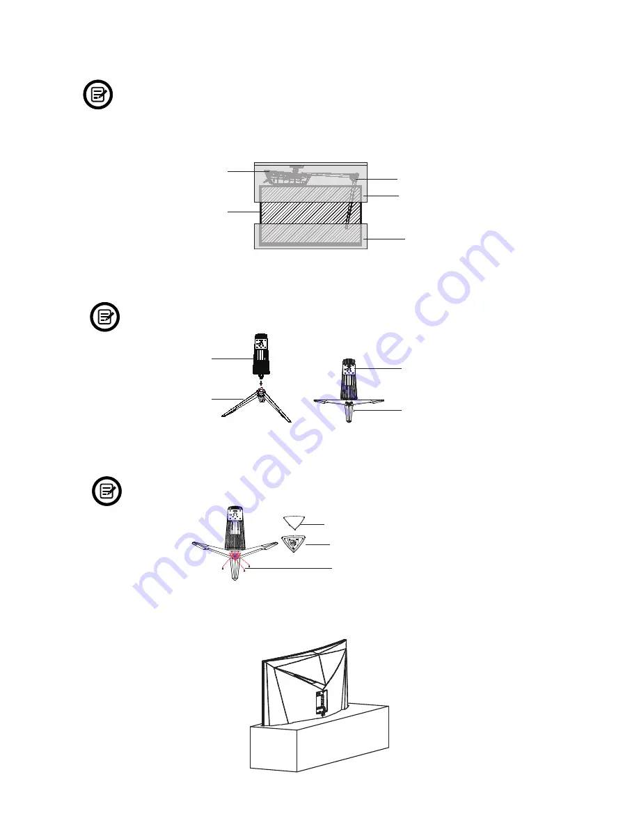
Section 4:  Stand Installation

  Keep the foam over the monitor before attaching the Stand. Follow the steps below to 

finish the installation.

1.   Open the package, take out the product with foam still attached, and gently place it on a 

desktop or table.

Monitor

Stand Base

Foam

Foam

Stand Stem

2.  Take out the two parts of the stand and use the included allen key and the NO. 1 screw to 

attach them.

          Use only the NO.1 screw provided.

Stand Base

Stand Stem


NO. 1 Screw (1x)

Bracket

3.  Take out the Cover Base, insert it into the stand near the base and secure it with three 

NO. 2 Screws. Next, place the Cover over the  Cover Base and press lightly to secure.


        Use only the NO. 2 screws provided.

NO. 2 Screws (3x)

Cover

Cover Base


4.  Take out the Monitor and remove the foam.

Summary of Contents for GN32LD

Page 1: ...OR CURVED GAMING MONIT USER MANUAL GN32LD ...

Page 2: ......

Page 3: ...e 10 6 2 Connecting Your Earphones 10 6 3 DP Connectivity 11 6 4 HDMI Connectivity 11 6 5 DVI Connectivity 11 Section 7 Basic Operation 12 Section 8 Indicator Light 13 Section 9 OSD Setup 14 9 1 OSD Menu Functions 15 Section 10 Troubleshooting 17 10 1 PIP Picture in Picture Input Information 18 10 2 PBP Picture by Picture Resolution Information 18 Section 11 Specifications 19 11 1 Resolution Compat...

Page 4: ...onitor 5 Do not spray cleaner and or any kind of liquid directly onto the monitor s screen or any part of the monitor 6 Do not insert anything into any part of the monitor especially the ventilation openings 7 Always make sure your monitor is placed on a secure level surface to prevent it from falling and sustaining damage 8 Unplug your monitor during any extended periods of non use 9 Do not place...

Page 5: ...et Stand Base x 1 Cover Base x 1 Cover x 1 Power Cable x 1 AC 100 240V 50 60Hz NO 2 Screws x 3 NO 3 Screws x 4 for Wall Mounting NO 1 Screw x 1 DP Cable x 1 Screwdriver x 1 Allen Key x 1 User Manual x 1 Note The NO 3 Screws come in two sizes 26mm x 2 and 31mm x 2 26mm 31mm ...

Page 6: ...the computer s DVI output and connect the other end to the monitor s DVI port 8 9 10 11 1 3 4 5 6 7 2 1 Power Connector Insert the Power Cable to supply power to the monitor 2 M Menu Button Press to display the OSD menu or enter sub menus 3 Down Button Press to move down in the menus 4 Up Button Press to move up in the menus 5 E Exit Button Press to exit 6 Power Button Press to turn the monitor on...

Page 7: ...am Stand Stem 2 Take out the two parts of the stand and use the included allen key and the NO 1 screw to attach them Use only the NO 1 screw provided Stand Base Stand Stem NO 1 Screw 1x Bracket 3 Take out the Cover Base insert it into the stand near the base and secure it with three NO 2 Screws Next place the Cover over the Cover Base and press lightly to secure Use only the NO 2 screws provided N...

Page 8: ...d click into place 6 Place the Monitor on your desktop or table after completing the installation and carefully pull or push it up or down to adjust the height Stand Stem 7 Press the button to and remove the Monitor from the bracket and to easily unmount it Button To avoid damaging the screen don t press down on the screen while placing it on the desktop or table ...

Page 9: ...onitor and then use the NO 3 Screws provided to secure the rear panel Do not discard the original screws They are needed to secure the rear panel for the stand installation Refer to Section 4 Use only the NO 3 Screws 31 mm x 2 pcs 26mm x 2 pcs provided You MUST follow the figure below to finish the installation Use the 31mm NO 3 Screws x 2 Use the 26mm NO 3 Screws x 2 3 Follow the directions recei...

Page 10: ...the power connector and then plug the other end into an AC outlet Power Cable Supplied 6 2 Connecting Your Earphones When earphones are plugged in no sound will be emitted from the speakers Earphones Not included Listening to loud audio for prolonged periods of time may permanently damage your hearing ...

Page 11: ...cluded 6 4 HDMI Connectivity In order for the Monitor to receive HDMI signals from the computer use the HDMI cable to connect the Monitor to the computer HDMI OUTPUT PC HDMI Cable Not included 6 5 DVI Connectivity In order for the Monitor to receive DVI signals from the computer use the DVI cable to connect the Monitor to the computer DVI Cable Not included DVI OUTPUT ...

Page 12: ... end to your power source It is recommended that you use a surge protector with adequate voltage if a wall outlet cannot be reached directly 4 Locate the power button on the Monitor and press it to turn the Monitor on If you cannot locate the power button please refer to the Product Overview Section on page 6 AMD FreeSync If desired you can use the monitor s AMD FreeSync feature The feature itself...

Page 13: ...een white light indicates power is on and the monitor is operating normally Flashing blue light indicates no video source has been detected Red light indicates that no horizontal or vertical signal has been detected or power is low Please ensure your computer is on and all video cables are fully inserted and or connected ...

Page 14: ...nter the OSD screen Figure 2 DP Resolution 2560x1440 60Hz Input Source Brightness Contrast Color Setting Picture Quality Setting Display Multi Window Audio Other DVI HDMI DP Window 1 InputSource DP Resolution 2560x1440 60Hz Window 3 InputSource Resolution Window 2 InputSource Resolution E Figure 2 3 Press or to browse functions a Highlight the functions you want to set and press M to enter the sub...

Page 15: ...Hue Saturation To set the hue and saturation of the display Picture Quality Setting Bypass On Off Turn the bypass function on off Sharpness 0 100 To set the the display sharpness Response Time Off High Middle Low To increase the response time of the monitor Noise Reduction Off High Middle Low To reduce the interference of image noise caused by signal source interference Super Resolution Off High M...

Page 16: ...ly the PIP PBP 2 screens function Other Language English 简体中文 한국어 Español Sets OSD language OSD H Position 0 100 To adjust the OSD horizontal position OSD V Position 0 100 To adjust the OSD vertical position OSD Transparency 0 100 To set the OSD overall transparency OSD Time Out 5 100 To set how long the OSD remains open after non use OSD Rotation Normal 90 180 270 When the user flips the display t...

Page 17: ...re The monitor needs cleaning Make sure the monitor has been powered off before cleaning Always use soft non abrasive cloth when cleaning Use dry non abrasive cloth to gently remove debris or dust If necessary lightly dampen a non abrasive cloth with water and gently clean the surface Never use alcohol or ammonia based cleaning solutions Never spray liquid directly onto any part of the monitor The...

Page 18: ...eature is supported while X means it is not supported 10 2 PBP Picture by Picture Resolution Information While using this feature and in order to obtain an optimal viewing experience it is recommended to set both panels to the same resolution It is recommended to set the first panel to 1440p 60Hz resolution 1 It is recommended to set the second panel to 1440p 60Hz resolution 2 At this resolution t...

Page 19: ...perating relative humidity RH 10 to 90 non condensation Height Adjustment Yes VESA Mounting 75X75 Dimension With Stand 28 3 20 96 13 97 in L W H Weight Net Gross Weight 20 83 Ibs 13 92 Ibs 11 1 Resolution Compatibility for DVI DP System Requirements below are the minimum system requirements for your GN32LD monitor The requirements are recommended in order to properly use all of the monitor s featu...

Page 20: ... 855 229 9472 for service request When a product or part is exchanged any replacement item becomes your property and the replaced item becomes WP s property This warranty only covers technical hardware defectiveness during the warranty period and under normal use conditions WP does not warrant uninterrupted or error free operation of this Product This Warranty does not cover any damage due to a tr...

Page 21: ... with the instructions may cause harmful interference to radio communications However there is no guarantee that interference will not occur in a particular installation If this equipment does cause harmful interference to radio or television reception which can be determined by turning the equipment off and on the user is encouraged to try to correct the interference by one or more of the followi...

Reviews: