


18/32
NT00000582-PILOT-PARC-MAITRE-AN-200723
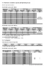
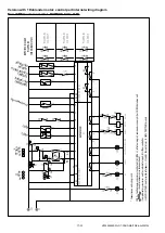
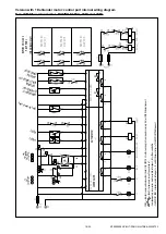
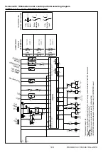
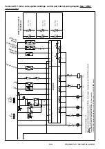
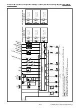
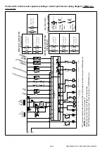
Version with 1 Dahlander motor: control part internal wiring diagram
Non-“CMSI” version model - RATINGS 150A, 185A and 225A
CONTROLLER
LOC
AL
STOP
Remote
RESET
SAFETY
Slave thermal relay
ERMERGENCY
SUHTOFF UNIT
AIRFLOW
CONTROLLER
HS
LS
SMOKE EXTRACTION
FAULT
AUT
O
HS
LS
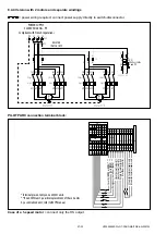
PILOT PARC
SLAVE N°1
PILOT PARC
SLAVE N°2
PILOT PARC
SLAVE N°3
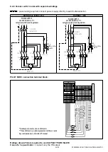
EXTERNAL
ISOLATOR SWITCH
REPORT ON SLAVE
PILOT PARC
(OR ON BMS/CTM)
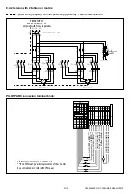
CO
NF
. = C
omfor
t command ex
ternal unit Auto/LS/HS (BC
CA 2S,
re
fer to wiring in § command accessor
y list) or C
O/NO2 detec
tion uni
t.
= shunts to r
emo
ve
in case of connec
tion of :
• C
omplemento
ry
accessories: isolator switch info r
epor
t ; HS air
flow contr
oller
.
• SL
AV
E PIL
OT
PARC (isolator switch info r
epor
t + LS and HS thermal r
elays),
cf. SLA
VE PIL
OT
PARC manual
.
AU
TO
MA
TO
N
12
3
3
2
1
3
2
1
3
12
3
1
1
GV
PV
CONF
.
KA
gv1
KA
pv
1
KMgv1
KMpv1
Q4
Q3
Q4
Q3
Q2
Q1
I4
I3
I2
I1
I8
I7
I6
I5
I4
I3
I2
I1
0V
0V
+UC
7
6
3
4
2
1
Rtpv
1
Rtgv1
8
9
10
11
0V
24V
3
1
B2
B1
V1
V2
A1
V4
13
14
51
52
22
21
96
95
96
95
14
13
14
13
A1
A2
14
13
V3
12
2
12
12
12
12
1
23
24
A2
A1
KMgv
1
KME1
KMpv
1
KMgv1KME1
KME1
KMpv1
A1
A2
14
13
A2
A1
A1
A2
22
21
22
21
21
22
F2
63
64
74
73
64
63
54
53
54
53
KMpv1
KMgv1
KMgv1
KMpv1
KMpv1
KMgv1
74
73
13
14
13
14
KApv
1
KAgv1
L2
L3
400Vac
F4
Q2
Q1
EASY
-E4-UC-8RE1
EASY
-E4-UC-12RC1
+UC
0V
14
13
INTZ


